papasfirstname is Nelson
so , papasfirstname@passlabs.com is equally functional as ******@passlabs.com
go figure
so , papasfirstname@passlabs.com is equally functional as ******@passlabs.com
go figure
papasfirstname is Nelson
Ah, I sent it wrong. You always kiding....
")
Now I understand I send it again
Thank you
It did not come back yet, somewhere went, maybe to you ZM
Last edited:
see , that's good idea ....... I'm going now to register that email , so from now on ,will intercept entire Papa's correspondence
(they already owe me opldf@passlabs.com addy , but their Administrator is lazy)

(they already owe me opldf@passlabs.com addy , but their Administrator is lazy)
Ah, I sent it wrong. You always kiding....
Now I understand I send it again
Thank you
It did not come back yet, somewhere went, maybe to you ZM
I got the message this morning from Desmond, who retrieved it from a
bin on the server....
Send me your address.
Can I send you mine? I have the transformers, I just need the rest.
>
Greedy <
Hi all
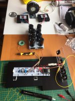
First power up of left channel.
No blown thingies, so that is good
But alas... 9mV from between R3/4 and GND so I presume I should fiddle with R3 and R4 values (both pretty exactly 10R now). Q3/Q4 are pretty close match as far as I know.
Any suggestion on value(s) to try?
And DC offset on outputs: With P1 at factory value (not measured) somewhere between -700mV and -800mV. P1 fully clockwise lowers this to about -280mV. So I am about to increase R7 to 56k. Or should I jump higher? Have 68k and 73k2 on hand. Both R6 and R7 are 47k at the moment.
Steef
Attachments
buffer offset positive or negative?
Positive
regarding output offset - try first value you get in hand then you'll know more
Ok will do and report back
Thanks
Steef
One other quick question. Looked for it on the thread but did not find it (that could be me )
I was planning to put two mono volume pots at the back of the chassis for master volume adjust and volume matching (acoustically - nasty rooms). I had a NAD 916 a long time ago which had this and I found this very handy at the time. Any pot recommendations (at least which impedance to use)?
Steef
)I was planning to put two mono volume pots at the back of the chassis for master volume adjust and volume matching (acoustically - nasty rooms). I had a NAD 916 a long time ago which had this and I found this very handy at the time. Any pot recommendations (at least which impedance to use)?
Steef
Hmm
DC at Edcor: Parallelling 133R with R4 lowers R3/4 junction to GND from 0.009V to 0.007V. Parallelling another 133R (so 10R + 133R + 133R) lowers further to 0.006V
The DC offset at output jumped (with P1 full clockwise) from -300mV to +2000mV when increasing R7 from 47k to 56k. Fully turning P1 to counterclockwise lowers to 424mV
Steef
- Home
- Amplifiers
- Pass Labs
- Official M2 schematic