This is a little off topic for diy-audio, but it is the only forum I'm a member off that deals with circuitry. I have been trying to figure out how to design a circuit that can blink a high power led on and off. I have created an electro-mechanical blinking circuit but I don't think it will be reliable enough. I would like it to be solid-state.
Criteria:
- Handle 20a @ 36 VDC
- Solid-State
-Simple
-Reliable
-Led on 1 second, off 1 second
I don't want it to seem like I'm asking too much of anyone but I have googled and prototyped to no avail
The attached picture is a very over simplified version of how I need it to be.
Criteria:
- Handle 20a @ 36 VDC
- Solid-State
-Simple
-Reliable
-Led on 1 second, off 1 second
I don't want it to seem like I'm asking too much of anyone but I have googled and prototyped to no avail
The attached picture is a very over simplified version of how I need it to be.
Attachments
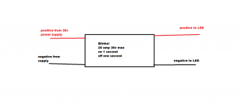
blink a high power led on and off. Handle 20a @ 36 VDC
Please give more details of the LED load.
I've not built anything like this before but seems to me you need an oscillator giving a 0.5Hz squarewave then this can be fed into a MOSFET to do the switching.
The oscillator can be created with a CMOS chip like CD4060, just choose the R and C values and divider tap-off point to get 0.5Hz. A suitable MOSFET can be found on Mouser's parametric search feature. You need a low RDS(on) or it'll get hot and need heatsinking. For 20A, 50% duty cycle a <4mohm FET in TO220 shouldn't need a heatsink but if you decide to use a small clip-on heatsink then you can go higher in RDS(on).
A quick scan on Mouser found this Toshiba FET - TK72A08N1 | MOSFETs / Junction FETs | TOSHIBA Semiconductor & Storage Products Company | Asia-Pacific
I've not built anything like this before but seems to me you need an oscillator giving a 0.5Hz squarewave then this can be fed into a MOSFET to do the switching.
The oscillator can be created with a CMOS chip like CD4060, just choose the R and C values and divider tap-off point to get 0.5Hz. A suitable MOSFET can be found on Mouser's parametric search feature. You need a low RDS(on) or it'll get hot and need heatsinking. For 20A, 50% duty cycle a <4mohm FET in TO220 shouldn't need a heatsink but if you decide to use a small clip-on heatsink then you can go higher in RDS(on).
A quick scan on Mouser found this Toshiba FET - TK72A08N1 | MOSFETs / Junction FETs | TOSHIBA Semiconductor & Storage Products Company | Asia-Pacific
Or you use this (with added power MOSFET circuitry) :
https://www.fairchildsemi.com/datasheets/FA/FAN5646.pdf
This is a "breathing" LED flasher so no hard off and on behavior.
Last edited:
Thank you for all of you're suggestions!
Here is a little more information, the led draws 100w at 35v which give a current of 3500 ma. This "blinker circuit" will not need to regulate the current, the power supply will go through the blinker circuit and then to the led. the reason I said I need the driver to handle 20a is to have the ability to expand, and power other devices.
I should have said this before, but this will be a sort of lighthouse/buoy near the water. so the 1 second on, one second off thing is kind of important. if it blinks any faster than this it will not meet regulation.
keep in mind I'I new to working with microcontrollers and such. I have electronics experience, but not with solid state devices. I have always used electro-mechanical devices.
sorry about the double post.
That chip looks to be exactly what I need! Now, would I just hook the gate of the mosfet to the LED output of that? And how would I program it?
That chip looks to be exactly what I need! Now, would I just hook the gate of the mosfet to the LED output of that? And how would I program it?
That chip looks to be exactly what I need! Now, would I just hook the gate of the mosfet to the LED output of that? And how would I program it?
No programming, have a look at the video to see its behavior. I think the sequence is the right one for you. It will way better for the power LED(s) to slowly blink ("breathing") instead of hard switching. The PSU will also thank you for it. You will need a heatsink with slow blinking I think as the MOSFET will dissipate more than with hard switching. I have to go so I hope the other members can help you further.
https://www.youtube.com/watch?v=E-8LVmGp_fs
Last edited:
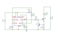
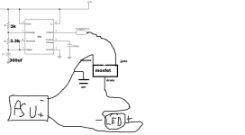
That chip in the circuit of post 10, requires no programming, it is an LM555 and costs a dime per dozen. C10 determines the frequency, R10 and R15 the mark space ratio. If you divide the capacitor by ten the frequency will increase by factor 10 and if you multiply the capacitor by ten the frequency will be divided by ten, how simple can it be? The MOSFET turns on and off hard so there is no heatsink required for the MOSFET, in fact an SMD can be used.
As it stands the blink rate is about 1 second on and one second off as you require.
The MOSFET can be replaced with MTDL3055 and Q1 as well as R16 can be left off if your LED is already current controlled. The whole circuit will probably cost no more than $2-00
As it stands the blink rate is about 1 second on and one second off as you require.
The MOSFET can be replaced with MTDL3055 and Q1 as well as R16 can be left off if your LED is already current controlled. The whole circuit will probably cost no more than $2-00
Last edited:
That chip in the circuit of post 10, requires no programming, it is an LM555 and costs a dime per dozen. C10 determines the frequency, R10 and R15 the mark space ratio. If you divide the capacitor by ten the frequency will increase by factor 10 and if you multiply the capacitor by ten the frequency will be divided by ten, how simple can it be? The MOSFET turns on and off hard so there is no heatsink required for the MOSFET, in fact an SMD can be used.
As it stands the blink rate is about 1 second on and one second off as you require.
The MOSFET can be replaced with MTDL3055 and Q1 as well as R16 can be left off if your LED is already current controlled. The whole circuit will probably cost no more than $2-00
The 555 is an old but still a very nice chip but would it be possible to let the power LED "breathe" to prolong LED life ? I would not hesitate to use the circuit but with 3.5A soft switching seems better. I don't know if it has to be a cheap solution but some refinement would not hurt if costs are low. C10 should be an X7R ceramic cap and not an electrolytic cap if the device will be used outdoors.
Some really love the 555:
555 Footstool | Evil Mad Scientist Laboratories
And not that there is anything wrong with the blinking approach, as an alternative, a steady light with a moving shutter in front of it will create the same effect to an observer.
OP said he wants a solid state solution and not electro-mechanical. It's 2015 already
Last edited:
That chip in the circuit of post 10, requires no programming, it is an LM555 and costs a dime per dozen. C10 determines the frequency, R10 and R15 the mark space ratio. If you divide the capacitor by ten the frequency will increase by factor 10 and if you multiply the capacitor by ten the frequency will be divided by ten, how simple can it be? The MOSFET turns on and off hard so there is no heatsink required for the MOSFET, in fact an SMD can be used.
As it stands the blink rate is about 1 second on and one second off as you require.
The MOSFET can be replaced with MTDL3055 and Q1 as well as R16 can be left off if your LED is already current controlled. The whole circuit will probably cost no more than $2-00
I was talking about the fairchild led chip needing to be programmed. But I have used the 555 before. So the circuit I posted earlier, with 555 should blink on every other second. I just need to know how to use the 555 to switch a mosfet on and off to control the 35v supply.
- Status
- This old topic is closed. If you want to reopen this topic, contact a moderator using the "Report Post" button.
- Home
- General Interest
- Everything Else
- Off-topic -- High power Led blinking circuit