Wave-length is the key parameter here. At 20 Hz we are talking 17 meters....
I am no horn expert at all, but if I'm not mistaking, the effective length of the horn mouth (from driver to opening) must be at least 1/4 wavelength for the horn to be effective. At 20 Hz that means 4,25 meters. Quite a lot.")
I am no horn expert at all, but if I'm not mistaking, the effective length of the horn mouth (from driver to opening) must be at least 1/4 wavelength for the horn to be effective. At 20 Hz that means 4,25 meters. Quite a lot.
On second thought: Could the angled side function as a wave guide in the bass region?
A lot of different cardioids here:
http://http://kotisivu.dnainternet.net/anukaa/CardSub/CARDSUB.html
A lot of different cardioids here:
http://http://kotisivu.dnainternet.net/anukaa/CardSub/CARDSUB.html
Last edited:
Open baffle bass loading with front horn
Hi Silent Screamer,
Let me say upfront Stig is the best reference for all things open baffle, his amazing work on this site is simply unmatched.
Back in 2004 I spent a lot of time experimenting with open baffle but I was only interested in frequencies below around 500Hz.
In summary my conclusions are:
(1) NON symetrical side wings are great ie take uneven "shark bites" out of them and this gives significant low frequency boost, adds body and texture to the low mids without ANY nasal vocals or honky colourations that come with straight symetrical side wings.
(2) Shallow front loaded horns are great and dont need to be too big to get worthwhile gains ie 3dB to 4dB gains are easily achievable with just 150mm (6 inch's) front to back depth and 560mm (23.5 inch) square mouth opening. See links
http://www.ddshorns.com/BassMid DVB 15H.pdf
http://www.ddshorns.com/BassMid DVB 15N pro.pdf
http://www.ddshorns.com/BassMid DMB 12N pro.pdf
(3) Certain Beyma and Precision Devices Pro drivers make great music in open baffle. At the other end of the scale some 8 and 10 inch Hi Fi drivers can work if doubled or used in line array, but the golden rule of "size matters" really is key with OB bass.
(4) Below 35Hz to 45Hz best to use sealed box sub(s) ideally three or four 12 or 15 inch drivers.
Hope that helps!
Cheers
Derek.
Volt 10 inch BM2500.4 in small open baffle
Hi Silent Screamer,
Getting back to how far does a cone move / need to move to reproduce a given frequency at a given SPL...Here is a photo ( post 26) of a pair of my Encore speakers...The 10 inch cone never showed visable movement...Even with huge power amps directly connected ( all my speakers are full active designs). Max SPL was above 115dB in the room at 1 meter, the Manger ran out of headroom first!
http://www.diyaudio.com/forums/swap-meet/155426-aladdin-s-cave-clear-out-sale-3.html
Covering 100Hz to 500Hz the The small baffle ( from memory about 300mm wide by 350mm tall) and deep side wings ( VPL - "Variable Path Length" 200mm to 400mm boosted the low end performance by over 4dB with ZERO sonic penalties.
Cheers
Derek.
Ok so I tried to find out what wavelengths are all about so I looked up Wiki... What a waste of time that was. If I wanted to know how many burgers Bobby needs to flip to for a electronic sine wave to reach the speed of water they have a formula for that, but answer a simple question of how to calculate a wavelength without a history lesson on why they use Greek characters to represent wavelengths is not on there.
I did manage to decipher one of the codes to find out that wavelengths are simply calculated by taking the speed of sound (343 m/s under normal atmo and temp) dividing it by the frequency in question, and reading the answer in meters.
So as StigErik said before the wavelength of 20Hz signal is 17.15 meters (343 / 20 = 17.15) and we need at least a quarter wave 17.15 / 4 (to get a quarter) = 4.29 meters.
Now the bit I don't know... how does the sound wave propel itself off the driver cone? i.e does it go straight, it is based on the angle of the cone? The how does it begin to propagate the sound wave?
How wide is a sound wave? (I figure the longer the wave the narrower it would be peak to peak???)
If someone could please explain those in layman's terms (without Greek formulas) I might be able to make some sense of a decent baffle shape.
Thanks Derek that is interesting. Just looking at those specs it would appear obvious that the length is to aid the low end more so than the high end.
I notice on the 15" that the dimensions for the 60Hz up was Dimensions 22"H x 22"W x 15"D
I have about 12" deep and could potentially make it a bit deeper, the horn must be fairly tight if the outer dimensions are 22" and there seems to be distance to the sides.
22" - 1" each side = 20" - 15" driver / 2 = 2.5" each side.
Yes I do try to absorb as much of StigEriks posts as I can for that reason.
Just looking they seem to vary from 5.7" to 15" so perhaps the idea might work after all.
Last edited:
Pic of open baffle shape
http://www.diyaudio.com/forums/multi-way/100392-beyond-ariel-510.html#post1794325
Post 5100
Now use this principal with a single 15 inch and add on to the front a DDS style front loaded horn 560mm by 560mm by 150mm deep and you will have the best of all worlds down to the FS of the bass driver.
Cheers
Derek.
150mm deep DDS horn is best
Hiya,
Check out the other 15 inch DDS horn, its only 6 inch's deep and adds over 3dB to the efficiency.
Some where in my old threads / posts I have posted a pic of an MDF baffle based on this horn ( I only used 4 in chch deep) using a pair of 15 inch Precision Devices 15 inch drivers...Killer sound!
Cheers
D.
"Free" Acoustic boost is better than DSP boost
Hiya,
For sure 3dB is a great help, its so much better to get a few dB acoustic boost with cabinet design rather than adding more Eq boost with a DSP.
I love the DEQX DSP but it is very expensive and let down to some degree by the DAC's & A to D, power supplies etc.
But the core DSP is still King of the Hill in my experience.
Cheers
D.
Aren't you talking about two different things now?
If both sides of the "frame" exhibit the same spl ... the cancellation will still occur at the same frequencies dictated by the size of the frame/baffle. You've boosted output is all.
If one sides spl is greater that the other, you have changed the cancellation scheme ... but this also begins to depart from a true dipole as a result. (cardioid instead?)
What is the goal?
Baffle width / lowest Fs
Hi Puppet,
Two different techniques to accomplish the same goal, which is lowest distortion & lowest colouration combined with maximum efficiency and high SPL capability.
(1) Increasing effective baffle width will increase bass extension i.e. lower the frequency at which front to rear cancellation kicks in.
(2) Varying this width (path length) results in an even spread or gradual roll off rather than a "sharp step". This is very important for natural bass reproduction, but VPL is often overlooked despite being easy to implement and having no downside.
(3) Adding a shallow front horn or wave guide (like the 6 inch deep DDS) further extends the effective baffle width by half the width plus half the depth. It helps to do a scale drawing in plan view of your driver / baffle / horn and work out the total front to rear path length from centre of dust cap to rear centre of magnet.
Then divide this length in mm by two and you this gives you the effective baffle width, then calculate the corresponding wavelength of sound and Voila you have the cut off frequency.
(4) Using a VPL will mean you measure the minimum ( the deepest part of the "shark bite" path length and the maximum ( little or no bite ) and then you have the " range" over which cancellation will gradually and smoothly take place.
(5) The front shallow front horn will also add 3dB or 4d to efficiency by reducing the impedance of the air load "mismatch" between the Sd of the driver and the Sd of the room it is meeting. In its simplest form it allows a more gradual transition in the horn from 1 square foot ( driver Sd) to 160 square feet if you imagine a 20 ft. wide by 8 ft. tall room, this is a 1 in 160... The 2 ft. by 2 ft. square horn mouth has a Sd of 4 square feet so this is a ratio of only 1 in 40, a huge improvement for a little extra cabinet work.
Hope this helps.
Cheers
Derek.
Hiya,
For sure 3dB is a great help, its so much better to get a few dB acoustic boost with cabinet design rather than adding more Eq boost with a DSP.
I love the DEQX DSP but it is very expensive and let down to some degree by the DAC's & A to D, power supplies etc.
But the core DSP is still King of the Hill in my experience.
Cheers
D.
Yes I am very happy with my Ground Sound DCN28, it doesn't look as flash as the DEQX but it certainly does the job very well.
But don't let the demure looks fool you under the hood there is a savage big cuber.
Because I am working with unknown drivers it is hard to say conclusively, but active seems to deliver a clarity and cleanliness that passive doesn't, and the difference isn't subtle.
Really glad I chose to go active
Two good posts 92 & 93 as I just come to realise that I was trying to cancel out the cancellation with SPL not based on the sound wave.
Great post Overkill Audio, I followed most of it. If you please back it up with some diagrams that would be fantastic. Please don't add any more info just the same thing in pictures to make sure I have understood it.
Great post Overkill Audio, I followed most of it. If you please back it up with some diagrams that would be fantastic. Please don't add any more info just the same thing in pictures to make sure I have understood it.
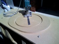
while drifting off to sleep last night I started thinking about how to form a horn for a test mule. I have a decent router and a large hole cutter, I was thinking of making some MDF rings and taper the inside edges. Glue them together and trap them between the speaker mounting board and the front facing baffle board.
But if the goal is to create uneven path length I might go higher than wider to create this effect. I could also try a piece sectioned horn but that might be a bit trickier, although much less MDF waste.
Penny drops why those short horns were more oval than round...
But if the goal is to create uneven path length I might go higher than wider to create this effect. I could also try a piece sectioned horn but that might be a bit trickier, although much less MDF waste.
Penny drops why those short horns were more oval than round...
Last edited:
The larger the woofer, the better in an OB ! A small woofer will make more excursion noise, more harmonic and intermodulation distortion at a given loudness level. Your woofer with a suitable crossover (less than 400 hz) should sound as good or better than a smaller woofer.
The quest for Xmax is more important the smaller the driver you have and the lower the bass response you need.
The quest for Xmax is more important the smaller the driver you have and the lower the bass response you need.
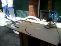
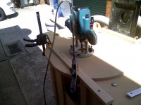
Decided to get outside and make some dust...
Because I want to start with a circle and turn it into an oval, I did some test cutting to see how it would go.
Need to see if I can purchase a 60 degree and 45 degree router bits for the inside cuts.
I would use the 60 degree on the straights, and the 45 degree on the half moon ends. That should allow me to join it to a rectangle baffle board.
Attachments
Sketch to show path length
Hiya,
It will probobly be next week before I can make up some drawings as I am traveling a lot this week and have a couple of all day presentations to prepare for.
Hopefully some others might be able to sketch something up...?
Its really just a shallow front horn fixed to the front baffle of an open baffle speaker.
To calculate the path length, imagine a piece of string glued from the centre of the dust dust cap running horizontally all the way round to the rear centre of the magnet.
Half the length of the string = the pathlength, assuming equal front & rear sound output.
That distance will = a certain wave length, which is the lowest frequency the speaker can reproduce.
Normally floor loading will extend the downward vertical pathlength to infinity, and the total height ( including the depth of the top of the cabinet) adds a good meter or more to the upward vertical path length.
Sorry for the extra description when all you wanted was a sketch...just not got enough time!
Cheers
Derek.
Hiya,
It will probobly be next week before I can make up some drawings as I am traveling a lot this week and have a couple of all day presentations to prepare for.
Hopefully some others might be able to sketch something up...?
Its really just a shallow front horn fixed to the front baffle of an open baffle speaker.
To calculate the path length, imagine a piece of string glued from the centre of the dust dust cap running horizontally all the way round to the rear centre of the magnet.
Half the length of the string = the pathlength, assuming equal front & rear sound output.
That distance will = a certain wave length, which is the lowest frequency the speaker can reproduce.
Normally floor loading will extend the downward vertical pathlength to infinity, and the total height ( including the depth of the top of the cabinet) adds a good meter or more to the upward vertical path length.
Sorry for the extra description when all you wanted was a sketch...just not got enough time!
Cheers
Derek.
- Status
- This old topic is closed. If you want to reopen this topic, contact a moderator using the "Report Post" button.
- Home
- Loudspeakers
- Multi-Way
- OB Bass Excursion