Simulations use planar drivers, so they cannot show eg. cone/dome geometry effect and resonances which typically happen above 3kHz.
With dipoles, rearside response can be very different from frontside, where all optimization is typically done. This is very important to remember with ob-dipole designs. Measurements of chosen drivers in test baffles are needed, 0-180deg horizontally and also some verticals, which sadly are always bad on multidriver systems.
With ob, rearside dispersion is important because total sound power and decay at listening spot is what we listen to. Axial or typical "listening window" average is not enough! In theoretically best dipole, front and rearside dispersion are mirrorlike, but we must always be satisfied with a reasonable compromise. In nearfield axial response is most important, but that waydipoles don't show their virtues.
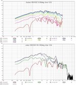
All following spectrograms are normalized to axial response!
Dipole with horn 0-80deg

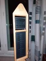
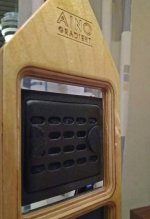
AINOgradient Neo83 0-180deg

And now I found 0-180 deg of a typical 5# cone driver in narrow baffle dipole, measured by me

With dipoles, rearside response can be very different from frontside, where all optimization is typically done. This is very important to remember with ob-dipole designs. Measurements of chosen drivers in test baffles are needed, 0-180deg horizontally and also some verticals, which sadly are always bad on multidriver systems.
With ob, rearside dispersion is important because total sound power and decay at listening spot is what we listen to. Axial or typical "listening window" average is not enough! In theoretically best dipole, front and rearside dispersion are mirrorlike, but we must always be satisfied with a reasonable compromise. In nearfield axial response is most important, but that waydipoles don't show their virtues.
All following spectrograms are normalized to axial response!
Dipole with horn 0-80deg
AINOgradient Neo83 0-180deg
And now I found 0-180 deg of a typical 5# cone driver in narrow baffle dipole, measured by me
Last edited:
Those plots are very interesting.
As mentioned, it's going to be many years of fun. The good part is I threw the drivers in a random baffle and it sounded really good, good enough to just enjoy. So none of it is torture.
I look forward to measuring my drivers. I won't be changing the drivers but will work with what I have the best I can.
Juhazi, that basta response I posted earlier, without any real concerning dipole peak ..any explanation for that? Shouldn't I be seeing something more around 2-3k? Or am I wrong?
Just want to simulate the best I can so I don't have to make 30 different trial and error baffles.
Hi @Juhazi,
I was wondering, if you could comment of the figures in your post #21, as I do not understand how to interpret it.
As I understand the first figure, the frequency range 20 Hz - 1200 Hz, seems to indicate a proper cancellation due to front to back radiation, limiting the directivity from +45 to -45 deg.
The remaining frequency range 1200 Hz - 20,000 Hz has directivity decreasing from +-45 deg to +-22 deg. However, this does not appear to be due to cancellation, but directivity of the driver(s) covering the frequency range.
If the above interpretation is correct, is the problem that the device is not dipole throughout its operating range? On the other hand, if a (near) constant directivity is the aim of the design, the device appears to satisfy that.
Kindest regards,
M
Last edited:
First graph in post #21 is a speaker with a coaxial consisting a large woofer and a small horn. You can see many such speaker at diyaudio.co "Open baffle gallery" I don't remember what it was exactly (not mine)
Constant directivity in frontal sector was achieved, yes. But as a hifi speaker is supposed to be positioned standing away from walls in a normal living room, it will sound strange. Almost total lack of rearside radiation above 1kHz, it's room response including reflections from front- and side walls make it's sound and decay unnatural. Many users add some kind of extra rearside tweeter/horn to get more balanced decay in-room.
But with careful 4-way dipoles like Charlie Laub's dipoles, my AINOgradient, Linkwitz's LX521 and Kreskovsky's NaO Note III true and even dipole pattern can be reached up to 6-8kHz. Each unit should be lowpassed below dipole peak (where pattern is true dipole). Above 6-8kHz physics become impossible, but that range is relatively unimportant.
AINOgradient's have monopole bass, because I can't have very large woofers and lots distance to front wall. Combination of mono and dipole around LR2 xo give cardioid pattern, which is the really unique feature of original Gradient 1.3 series by Jorma Salmi.
I am preaching about true dipole radiation, because these speakers really do sound natural and spacious unlike any others. This requires also very symmetrical positioning and room. Flat axial response and smooth frontal directivity are enough for nearfield monitoring only IMO. Another good wdy for natural stereo is in-wall speakers with wide and smooth pattern. But I know people who like eg. synergy horns or other very narrow-directivity designs - nothing wrong with having different preferences..
Last edited:
Hi @Juhazi,
thank you for your reply. In view of that, I can now understand the other two figures in the above-mentioned post.
I understand from your post that your and others' preference is for a (nearly) full dipolar radiation. I do not want to get into a discussion about subjective preferences, but I note that there are many (even highly regarded designs, cf. Clayton Shaw's), that do not have dipolar radiation throughout the entire frequency range.
In other words, the beauty is in the ear of a beer holder.
Kindest regards,
M
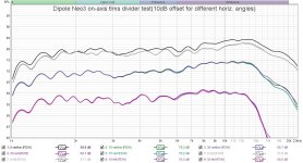
@Juhazi correct that above 6khz physical driver size has to be smaller to make constant directivity all the up 20khz. This is what i get for that reason. But how is that possible that your second picture in post #21 has no this directivity widening like mine? Construction looks more or less the same as yours.Above 6-8kHz physics become impossible, but that range is relatively unimportant.
I think I want to look more seriously at down firing the sub. I do like the idea of being able to keep the mids around ear height. I've read through a lot of pass's slot loading, but fo you have any favorite resources for down firing sub building?Personally, I found subwoofer section ( below 80 Hz) definitely needs baffle, otherwise the dipole cancellation will be too much to handle even with 18“ sub. Midrange and tweeter above 400-500 Hz should have as narrow as possible baffle or even no baffle to make the dipole peak as high as possible to control directivity to higher frequency. The lower mid section (80Hz to 400 Hz) is a grey area. If driver is small like 8“ then some baffle is ok but the shape should be something like the one in LX521. If you use 12“ driver then no baffle is my choice.
About diffraction, the baffle edge diffraction at midrange and treble is a most difficult thing to fix so it is better to get
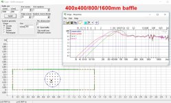
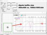
if you look the graphs it's kind of obvious the dipole peak gets worse the bigger the baffle, opposite from the quote
Square baffle with driver dead center, yes it would be worse.
Not really proving much other than here is a example of the 2 worst baffles to possible use.
And where to mount driver to yield worst results.
Thats an amazing graph! Do you have a build thread?@Juhazi correct that above 6khz physical driver size has to be smaller to make constant directivity all the up 20khz. This is what i get for that reason. But how is that possible that your second picture in post #21 has no this directivity widening like mine? Construction looks more or less the same as yours.
View attachment 1313282
View attachment 1313286
@Juhazi correct that above 6khz physical driver size has to be smaller to make constant directivity all the up 20khz. This is what i get for that reason. But how is that possible that your second picture in post #21 has no this directivity widening like mine? Construction looks more or less the same as yours.
View attachment 1313282
View attachment 1313286
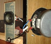
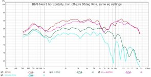
Looks like your speakers actually have larger baffles than mine. But your tweeter is mounted vertically (mine horizontally) Therefore radiating membrane width is shorter.
Second - My tweeter is on the bakside which makes a cavity on the frontside that has resonance. My rearside response is smoother!
Third - what was your measuring distance and settings for gating and smoothing?
The reason why I mounted horizontally is that the plywood plates were CNC'd for the previous version with horn tweeter. Later on I installed felt pads to make membrane narrower - it helped a little. Cardboard cross didn't have remarkable effect.

Last edited:
How many 18sw450 do you want to use per channel? If only one, then there is easy to keep the mid around ear height. 18sw450 has diameter of 46.5 cm, which mean if you use narrow vertical baffle (and wide horizontal), you can get away with 48cm height baffle. JBL 123a is 12", so the baffle for it can be as short as 36 cm. So baffle for two of them will be at 84cm. Sonido SWR-096A field coil is a 9"x6" (24 cm x 17 cm) driver. So if you use it without baffle, you can have the Sonido at either 96 cm or 90 cm, both of them are normally at ear height when you sit. If your ear height is higher than that value, you can increase the height of the baffle for 18SW450.I think I want to look more seriously at down firing the sub. I do like the idea of being able to keep the mids around ear height. I've read through a lot of pass's slot loading, but fo you have any favorite resources for down firing sub building?
For down firing subs, I never consider that option. But I remember Troels Gravesen have some big floorstanding with this option, so you can check his website
Square baffle with driver dead center, yes it would be worse.
Not really proving much other than here is a example of the 2 worst baffles to possible use.
And where to mount driver to yield worst results.
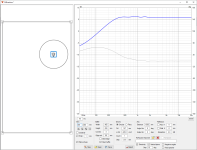
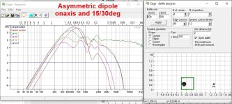
Dead-center mounting on circular baffle is worst scenario - when we look at response and dispersion above dipole peak. A dipole shoud be lowpassed anyway, so this is not a problem for multiway dipoles. Sadly 95% of "open baffles" don't follow this advice...
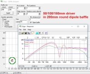
Last edited:
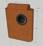
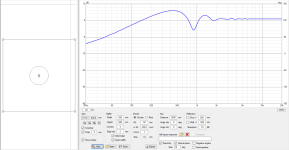
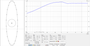
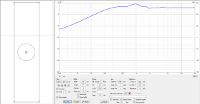
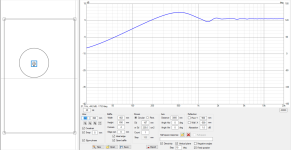
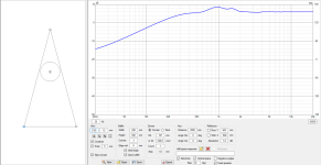
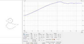
Here is few random shapes in addition to what Juhazi already postedSquare baffle with driver dead center, yes it would be worse.
Not really proving much other than here is a example of the 2 worst baffles to possible use.
And where to mount driver to yield worst results.
Square

Surfboard

Tall rectangle

Golden ratio

Triangular

Duck

And finally no baffle
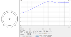

It's quite easy and fast to churn out any shape and then realize the no baffle is actually pretty good. Saying it's the worst is only true on some particular context. It's worst on one driver system, because it has least bass. In terms of edge diffraction problems in listening window it's about as good as it gets, the hump can be EQ:d out.
The graphs here show interference pattern that emerges due to two sound sources, the transducer and the edge. Sound source at the edge has different bandwidth than the transducer, and is delayed relative to distance between transducer and the edge, and resulting path length difference changes to any observation angle, the further the edge the lower in frequency interference starts. There is plenty of gray area to debate when the secondary sound source makes difference in sound, for example all the above examples could sound just fine, db of wiggle here or there. But I'd say the farther and longer the edge, the more likely it is audible, after all it makes "more interference" on the graphs. It's reasonable to randomize the distance from transducer to edge to distribute the delays to reduce the interference wiggle, if it has to be big baffle. This ought to reduce audibility, if it was audible in the first place.
Point is not to fight, only that you saying it's worst or me saying it's best could both be true in one context and false on another, and plenty of grey between.
Last edited:
Hi,
some kind of rough simulation yes. You can do ideal omni bass first in diffraction simulator, turn and position the spinorama data in the main program so that it points towards "ceiling" for example. Also the baffleless top shape can be drawn and each driver measured (simulated) on that separately, and then in main program positioned above the woofer. Diffraction simulation like this are grude though, as the woofer object isn't there in top measurement (simulation) data and vice versa so you can't see how they interact as both are each others immediate acoustic environment. There is no full 3D shape and so on. But it's possible to get the positions / phase approximations somewhat close and then play with them. Any set of measurements done in reality or with any simulator, basically any driver + effect of structure, can be positioned relative to listening axis and each other with any x,y,z position, rotation and tilt and see what the combined response is at any observation angle.
It's also possible to make impossible arrangements, like everything colocated at same point in space which is not possible in reality, which allows you to reason about things and build intuition and imagination skills. Soon you are able to do this kind of simple sims in your head 😉
These simple sims would not reflect reality, as acoustic center of real drivers is very different than ideal flat disk in diffraction simulator, acoustic center changing with frequency for example, but if it's the shape of the system and relative positioning what you are interested in it's possible to do relative comparisons. You could simulate various shapes and play with heights and relative positioning and so on, even the impossible ones, to see what kind of a performance there is available and what is possible and what is not. Reality is always worse than idealized simplified simulation, so if your sim looks poo then built and measured in reality it likely looks even more poo, but it could still sound fine.
You could also play around and test things like what if acoustic center of mid was 2cm back and how big of a difference it makes 🙂 All sorts of stuff is possible, even though there are limitations. I like to think diffraction simulator as just virtual spinorama and use it just like VituixCAD measurement manual guides to use real measurements. Use the diffraction tool as you would measure a real box to get similar data as you'd get from real box, one driver at time. Then use the data in main program as you'd use it with real measured data.
For full 3D model sim BEM simulation is needed. It takes some time to whip up and simulate, could take a day. VituixCAD is nice for experiments it can do, as it's real time! BEM data can also be imported into VituixCAD.
Last edited:
Point is not to fight, only that you saying it's worst or me saying it's best could both be true in one context and false on another, and plenty of grey between.
Not trying to fight
You dont get it.
Any wavelength smaller than the piston has directivity
With no baffle the only frequencies not cancelled is essentially the same wavelengths.
Basically the only thing not cancelled is frequencies with directivity...LOL
you have rendered the speaker useless.
Your looking right at the pretty pictures.
Directivity never changes in all of them no kidding, piston size is the same.
Useable bandwidth is below directivity not above.
Remove the baffle completely, you have = nothing
How do you not see a huge dipole peak around
1.2 kHz with a 8" speaker on " No Baffle"
That basically instantly tell you nothing is there.
You cross over at 1.2 kHz with a 8"
Kinda hard to do if everything below that is....Zip
Hi,
I tried to demonstrate that the good bandwidth of a driver on a baffle is always from the dipole peak and down from that, perhaps few octaves before the sound is zip, nada, just like you describe. I totally see where the peak is and what it is and why it is. I also see the response drop, which is the cancellation. Also where a transducer beams, or has directivity as you say. It's all visible on the graphs, and all due to sound wavelength. You could take any of my examples and scale the size up or down and the response would look exactly the same, everything just shifts lower or higher in frequency depending on which direction you scale. The ideal simulations show 2" driver on 2" baffle has exactly same features of response as 15" driver on 15" baffle, the other has them higher in frequency than the other, because everything relates to wavelength.
What I demonstrated with the sims is that by increasing baffle size you move the cancellation to lower frequency, but side effect to it is that it drags the edge diffraction lower in frequency as well, and all it does it moves the whole good bandwidth lower in frequency but doesn't extend it much if you consider the edge diffraction sometihing to avoid. If you want to use big baffle you can, you can extend the usable bandwidth by increasing baffle size if you measure with the cancellation, there's just gonna be some edge diffraction on the pass band. Minimal baffle keeps edge diffraction issues on bandwidth where the driver would have all kinds of issues anyway, hense the logic. All problems pushed above low pass filter.
A multiway system can be built with various sized drivers either naked or in big baffle to achieve same system response and similar SPL capability. Difference is that the naked drivers don't have (that much) edge diffraction on pass band, as the system with small drivers on big baffles. Even if we discount the edge diffraction out from equation as unimportant, there is still lots more trade-offs with both approaches, like how to build it, how it looks, and so on. For example, if baffle size is much bigger than driver any resonance on the baffle would color the sound making it rather expensive. Say, you must decide how to cover 200-800Hz: using big expensive driver on free (non-existent) baffle could cost more or less, than small potentially cheaper driver on bigger more expensive baffle and both would have about similar output within the band. There is a lot to it.
Last edited:
Why useless? Below dipole peak we have constant directivity, which is a good thing. Make dipole peak higher by no baffle is extend this good area to higher frequency.Not trying to fight
You dont get it.
Any wavelength smaller than the piston has directivity
With no baffle the only frequencies not cancelled is essentially the same wavelengths.
Basically the only thing not cancelled is frequencies with directivity...LOL
you have rendered the speaker useless.
Your looking right at the pretty pictures.
Directivity never changes in all of them no kidding, piston size is the same.
Useable bandwidth is below directivity not above.
Remove the baffle completely, you have = nothing
How do you not see a huge dipole peak around
1.2 kHz with a 8" speaker on " No Baffle"
That basically instantly tell you nothing is there.
You cross over at 1.2 kHz with a 8"
Kinda hard to do if everything below that is....Zip
Worry about dipole peak at 1kHz, then make the crossover below that point and make some EQ to flatten the peak, use a smaller 4-5" midrange to handle the frequency above, problem solved.
- Home
- Loudspeakers
- Multi-Way
- OB baffle design options
