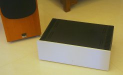
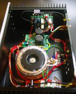
I've just posted up a write up and some pictires on my website (follow the link in my signature below) on my latest amp. This is based somewhat on the sx-Amp, which you may recall I posted up in August last year. However, that was a 15 W per channel class A amp whereas the nx-Amp is class AB 100 W. I am very pleased with the result - really great sound.
Bonsai, thank you very much.. i found many articles worth to read in your site.
Power Amplifiers articles is what i'm looking for
Thanks naf!
Hi Bonsai,
i'm start to read article on your site about Ovation 250 but when i've donwload schematic and read the article everything has changed totally different.
Circuit Description doesn't match with the schematic...
"The input is via J1 and into the non-inverting input transistor pair Q4 and Q7 via a 160KHz LPF filter formed by R28 and C10 ...... "
on schematic Q7 and Q4 is output Transistor.... please would you update and include original schematic so i can learn.
regards,
naf
Hi Bonsai,
i'm start to read article on your site about Ovation 250 but when i've donwload schematic and read the article everything has changed totally different.
Circuit Description doesn't match with the schematic...
"The input is via J1 and into the non-inverting input transistor pair Q4 and Q7 via a 160KHz LPF filter formed by R28 and C10 ...... "
on schematic Q7 and Q4 is output Transistor.... please would you update and include original schematic so i can learn.
regards,
naf
Hello naf
This is a design from 2006. I posted a new circuit diagram about a year ago. I will update text on th site in the next few weeks. Thanks for letting me know.
downloaded! i'll read slowly later, but it looks very good
Thanks Telstar!
Hello naf
This is a design from 2006. I posted a new circuit diagram about a year ago. I will update text on th site in the next few weeks. Thanks for letting me know.
Thanks a lot Bonsai,
even it's your design from 2006... this i new from me and worth reading it to gain my knowledge.
Bonsai, is the BC847 (SMD) in thermal contact with one of the Output devices or is it mounted to be in contact with the Heatsink? Due to unavailability of non-inductive power resistors and wanting to couple the nx-amp with a different protection circuit, I would like to make my own PCB (single sided, preferably). Hence, the question about thermal compensation scheme. Thanks.
Thanks Bonsai. So how is thermal compensation achieved? Thanks for your generosity with the THP Boards offer. I am a little doubtful about being able to source the NXP parts specified in the Protection Circuitry; hence, mine wanting to design my own boards with another protection scheme. However, I'll look at Element14 and RS for the NXP parts.
Another hint to those having trouble sourcing the specified TO126 transistors - 2SA1538 and 2SC3953 would be great replacements.
Another hint to those having trouble sourcing the specified TO126 transistors - 2SA1538 and 2SC3953 would be great replacements.
- Status
- This old topic is closed. If you want to reopen this topic, contact a moderator using the "Report Post" button.
- Home
- Amplifiers
- Solid State
- nx-Amplifier: 100 W CFA topology Amp