AKSA said:And clearly Kanwar has kept oscillation at bay......
Man, that's some achievement, particularly with mosfet output devices!
Congratulations, Kanwar, the Wizard of Bollywood!!
Cheers,
Hugh
Hello Hugh Dean,
Thanks for nice compliments...
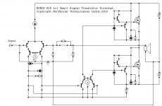
Yeah sure, its an achievement..All frontend is discrete on-board..no heatsinking required...except for the output devices....
regards,
K a n w a r
True Amplifier Guru
Thanks Kanvar
I like your schematic. Learned a lot from the way it evolved.
You are a true Amplifier Guru.
We appreciate your work, because it brings forth material that helps others, and it does so free of charge.
I see no price list, and no Visa/MasterCard/Paypal logo in the corner.
Glory to all those who help others with practical, actionable advice.
This is what makes a true Guru.
Andy
Re: True Amplifier Guru
Hi Andy,
Thanks for the Nice Compliments..very much....
regards,
K a n w a r
vectorplane said:Thanks Kanvar
I like your schematic. Learned a lot from the way it evolved.
You are a true Amplifier Guru.
We appreciate your work, because it brings forth material that helps others, and it does so free of charge.
I see no price list, and no Visa/MasterCard/Paypal logo in the corner.
Glory to all those who help others with practical, actionable advice.
This is what makes a true Guru.
Andy
Hi Andy,
Thanks for the Nice Compliments..very much....
regards,
K a n w a r
darkfenriz said:I guess bias adjustment and thermal sensing is in ccs, right?
Not at all, Its in the Rush Cascode...

Hi Kanwar
I do like it , the input and second stages look a little bit like an upside down version of the one I'm working on. I do particularly like the compound transistor / FET output stage. It seems as though you have the second stage driving into what is notionally a PNP output stage but is actually N-channel (if that makes any sense ..lol) and that is very clever. In conjuction with the associated NPN it must also provide very good control of the FET gate....very clever.
I don't know what rails you intend for this amp or what the resistor values are, but are there any heat issues for the MSA42/92 on the output stage?
Cheers
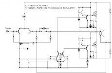
Workhorse said:Here's the DIY version.....
Where do you buy that circle component with an arrow inside it?


(Oh,.. and don't get me started on that circle component with a "V" inside it!)
This is a true story:
I was once in a Radio Shack store and a guy comes in with a schematic, and shows it to the store clerk. He was looking for a current source component from that schematic. After scratching his head for a while, the salesman proceeded to the parts section, and scratched his head some more once there. (I tuly wonder what it is he was hoping to find...)
Finally he emerged, victorious, holding a part in his hand "I think this is it!"
(It was a little blue trimpot, which looked like a disk with an arrow embossed on it)
"The most common value that people ask for is 1K" he stated confidently.
(Oh... a lot of people ask for 1K current sources, do they....)
The customer keenly noted that this part had 3 terminals instead of 2. to which the salesman had a snappy reply: "Oh, it's typical to use just two of the pins on this thing, the center, plus one side pin."
As payment was about to be made, I quietly moved in and pointed out that his schematic was probably not buildable, and that it was a concept schematic. They both looked at me with clear disbelief, and the store clerk looked visibly annoyed that I was questioning his expertise in front of another customer.
"You can bring it back if it doesn't work..." was the magic statement that relieved the tension and brought a comforting end to the transaction.
The funniest part of this, is that it might actually work (although not optimally). So these men must be credited with discovering that you can approximate a current source with a resistor, entirely by accidemt...
The most dangerous creature is a man who doesn't know, but thinks he knows...
quasi said:Hi Kanwar
I do like it , the input and second stages look a little bit like an upside down version of the one I'm working on. I do particularly like the compound transistor / FET output stage. It seems as though you have the second stage driving into what is notionally a PNP output stage but is actually N-channel (if that makes any sense ..lol) and that is very clever. In conjuction with the associated NPN it must also provide very good control of the FET gate....very clever.
I don't know what rails you intend for this amp or what the resistor values are, but are there any heat issues for the MSA42/92 on the output stage?
Cheers
Hi Quasi,
Frontend differential runs at 1mA ..500uA each transistor...
Second Differential runs at 2mA..1mA each transistor...requires a copper clip heatsink for cascode only....
Drivers Run at 10mA with 12V max across them ..locked by 12V Zeners..Only the resistors feeding the zeners need to be around 5W rating....
Rails are +-120V...FETs are IRFP460....
Rail loss is 0.4Volts max with 16 OHM load.....
The Driver stage is actually a PUSH-PULL type..which ACTIVELY TURNS-OFF the FET, thus eliminating the Cross-Conduction and improves the Transient response at HF........
I am dreaming of an all SMD version of frontend for this amp...but i am busy very much...hope someone on this forum would make PCB design or I would have to do this all...pretty time consuming...
Thanks alot,
K a n w a r
+/- 120 volts ...oh my goodness !!
I like the Push Pull - that's what I meant by "In conjuction with the associated NPN it must also provide very good control of the FET gate....very clever."
Why do you have the resistor between the two emmitters of the push pull?
The 5 watt resistors explain where the heat goes, thanks.
If you like my PCB work ...I'd be happy to do the PCB for this one....but your gonna have to trade....lol
Anyway, nice work ...you the man!
Cheers
- Status
- This old topic is closed. If you want to reopen this topic, contact a moderator using the "Report Post" button.
- Home
- Amplifiers
- Solid State
- NVMOS amplifier