Would you mind make a schematic drawing of the nice simple PCB of yours?Here is mine: 12.6V rectifier and stabilizer for filament, 12V relay, and 20 Ohm wirewound resistor. Never blows up in peaces. The PCB contains also -80V bias rectifier.

Thanks in advance
")
I use CL80's in all applications. Also started to use Damper diodes to soft switch the B+ from the first cap to the rest of the B+ filter chain. It allows for slow start for a slow ramp up of the B+ without the high peak and dip as the outputs come on line. It works great!
Please explain what you mean by these "damper diodes to soft switch the B+ from the first cap to the rest of the B+ filter chain."
In the past I had considered putting a diode on the input side of the inductor on a CLC filter, in the hopes it would prevent oscillation of current thru the inductor between the caps on either side of it back and forth and back and forth... Sorry to ask such a basic question (it's been 45 years in software since my minimal electronics training), but how do I calculate the additional voltage drop across the diode in the forward direction and would it be significant? Can somebody recommend a hefty diode for the job (500 V, 500uF cap, 1.3H inductor, 2500uF cap on a 180-watt tube amp)?
Otherwise I was considering adding two other ways of damping the low-frequency oscillation: a resistor in parallel with the inductor (ruining its sharp q) and a resistor in series with a cap (across the output) to burn up & slow down the voltage changes (but it requires a big cap to damp optimally).
Would you mind make a schematic drawing of the nice simple PCB of yours?
Thanks in advance
Here you go:

The relay is powered from output of this regulator.
For a fixed bias amp, I power a protection relay coil from the raw filtered bias supply, to provide a mechanism for bias voltage failure. The NO relay contact is used to connect a low resistance (or just bypass link) across a soft-start resistor in series with the secondary HT winding.
Additonal functions can be integrated by using a FET to switch the relay coil, and use a long RC time constant FET gate drive signal from the bias voltage to give say a 20-30 second delay on relay energisation, which can alleviate B+ voltage overshoot (especially if ss diodes are used and output stage bias current is needed to keep B+ lower than filter cap voltage ratings or tube anode/screen ratings).
The above focusses on the long delay needed for output tube heaters to allow bias current to rise at the same time as B+ rises. I'm happy to use a suitably chosen NTC to alleviate transformer in-rush, and then when the protection relay kicks in to also help alleviate B+ capacitor in-rush or diode stress if they are of concern.
Which is very close to optimal, as amplifiers that do this seem to last much longer with less service issues.
The relay does not see much current so it does not need to be large but should have a flash suppressor capacitor across the contacts from the turn off surge as the inrush limiter will be cold at that point, so there can actually be more voltage across the contacts at turn off.
When using a relay you can also use a resistor, but high surge current rated resistors are not common and a bit pricey.
The downside of the less expensive inrush limiter is that they do fail and sometimes with a flame, so only put them in metal chassis away from other parts.
And don't put flaming inrush resistor on the return path side of primary.
Don't size resistor so many ohms the real fuse on hot side never blows.
Don't make relay controller so dumb it can't or won't close relay when
there's a short (and fire) that needs the fuse blown.
I'm just sayin' because I saw this recently in a SMPS, and it irritated me.
Some dweeb is surely gonna put out that fire with ... use imagination ...
Damn engineer wouldn't spend a few bucks to replace with an NTC
that wouldn't have caught fire, and could have blown the main fuse.
It really should have been on the hot side, but an NTC would at least
made his junk a little bit safer without redesigning the whole board...
No, he put that relay so it "wouldn't need" an NTC. Yeah, what...?
Me no engineer - me too dumb - thinking not job - shut up and test.
Last edited:
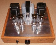
I use a CL80 on the 110 side of the transformer for inrush current control for the first cap. It allows for a smaller fuse to be used. Then C-DIODE-C-L-C. The diode bridge feeds the first cap, Now I place a damper diode as a pass device to another cap that feeds the subsequent filter and B+ bias string. I've done variants of this on many amps and also used it on a slow start for my RIAA and Preamp ( 12AL5 in this application).
The damper diode is the tube in the middle behind the 6550's.
The damper diode is the tube in the middle behind the 6550's.
Attachments
Here you go:
The relay is powered from output of this regulator.
Thank you very much Wavebourn.
The circuit looks great. I like the fet regulated heater supply.
Could you say something about the delay-time? The +B 300V from the gate of the fet?
Rgds.
Tube amplifiers
Wavebourn, you have made several tubeamplifiers for PA according to your site.
Soft-start for longer lifetime of capacitors and tubes is one issue, "overload" is another.
For home hifi it would be nice if the amplifier shuts down (or partially down) by overload ....may be depending on the amount of mA measured across the cathode resistor? ...like a DC sensor for solid state amplifiers.
Do you have any suggestions to a simple tubeamp overload protection, which does not affect the sound? ....in several tube designs with good reputation old tubes "runs" with bias and leaves us a red glowing plate and a tube melt down.
Can we do anything to avoid this?
Rick...
seeing your pictures,- have you looked at overvoltage suppressors?
For serious and sensitive installations, it is quite common to install a 'coarse' suppressor setup at the power intake, and another 'fine' suppressor in the relevant consumer line circuit ( going to your ampliifers and stuff) ....
seeing your pictures,- have you looked at overvoltage suppressors?
For serious and sensitive installations, it is quite common to install a 'coarse' suppressor setup at the power intake, and another 'fine' suppressor in the relevant consumer line circuit ( going to your ampliifers and stuff) ....
dont understand why tubes (as being recommended in general), should be heated first and later anode supply turned onEli Duttman said:When the amp. employs "fixed" bias, put the thermistor(s) in the rectifier circuitry. The idea is for the bias supply to turn on and protect against cathode stripping, before B+ is applied.
tube heaters when cold emits no electrons, so leaving them connected to circuit under full voltage cannot make them break.
Just piece of metals in vacuum
In my opinion, leaving everything normally connected is better than heating them up and later turning anode supply on. Risk of current spike through tubes
Vacuum rectif. has softstart "built-in", but the voltage sag is not nice.
I have tried a few different brands of these things and the GE Brand are by far the toughest. Their CL-80 works great for power amps drawing 1 to 2 amps continuous (digikey KC008L).
http://www.ge-mcs.com/download/temperature/920-325B-LR.pdf
I have had similarly rated ones from Cantherm fail. After a month or so they crack and open up. Maybe I have too much capacitance in the B+ to fill up, but it does not seem to bother the GE ones.
http://www.cantherm.com/products/inrush_current_limiter/cantherm_mf72.pdf
Wavebourn, you have made several tubeamplifiers for PA according to your site.
Soft-start for longer lifetime of capacitors and tubes is one issue, "overload" is another.
For home hifi it would be nice if the amplifier shuts down (or partially down) by overload ....may be depending on the amount of mA measured across the cathode resistor? ...like a DC sensor for solid state amplifiers.
Do you have any suggestions to a simple tubeamp overload protection, which does not affect the sound? ....in several tube designs with good reputation old tubes "runs" with bias and leaves us a red glowing plate and a tube melt down.
Can we do anything to avoid this?
It is what you can find in my Pyramid design: LED senses current drawn by screen grids and controls input attenuator LDR and "Overload" signal. No clipping, just hard optical compression when overloaded.
It DOES affect the sound, since it is compressed, but you SEE bright red LED when it happens and can turn the volume down.
Thank you very much Wavebourn.
The circuit looks great. I like the fet regulated heater supply.
Could you say something about the delay-time? The +B 300V from the gate of the fet?
Time constant depends on capacitors in power supply reflected by transformer ratios and current limiting resistor in the primary. It is _not_ a time delay, and I don't advocate any time delays in tube amplifiers that don't use Eimac transmitting tubes in factory specified regimes.
dont understand why tubes (as being recommended in general), should be heated first and later anode supply turned on
tube heaters when cold emits no electrons, so leaving them connected to circuit under full voltage cannot make them break.
Just piece of metals in vacuum
In my opinion, leaving everything normally connected is better than heating them up and later turning anode supply on. Risk of current spike through tubes
Vacuum rectif. has softstart "built-in", but the voltage sag is not nice.
You are absolutely right. Some tubes like transmitting and generating tubes were used in regimes that would cause huge current density from parts of cathode that start emitting before the whole cathode is hot enough that damages cathodes tearing parts from them off. Particularly, in the radar station of the anti-aircraft system we learned in the university as the part of compulsory additional defense education, such measures were implemented, as well as measures to prevent anode voltage from switching on until waveguide commutator is completely switched. But it is a different story: marketing people like to invent some features of their production to demonstrate how special it is, even when such features are not needed absolutely. Even harmful: abrupt appearance of anode voltage when cathodes are hot stresses tubes causing current in uncharged coupling capacitors between anodes and grids that causes positive voltages on grids, currents through grids, and high anode currents.
This happens here too !
Use a self excited relay so that power is not reapplied before YOU decide
Yves.
I built a latching relay into a Alesis Powertrip 8 but added an second tweak to the circuit - I installed a push to make switch in series with the coil and used a time delay relay - one has to hold down the pushbutton for 15 seconds before the relay energizes. This is my way of preventing casual visitors from turning on my system and my preamp, DAC's and source devices can be correctly sequenced in the event of a brown out (thuds be gone!). This is my little secret and helps keep my teenagers buddies away from my stereo.
I've taken out of dead PC power supplies the thermistor they use on the line side to limit inrush current. PC power supplies are rated around 100 to 250W, which is similar to the power consumption of tube amps. Even this crude engineering seems to work fine. The thermistor is placed on one of the primary leads of the power transformer. Done this in a SCA35 amp, now I don't hear the momentary loud transformer buzz upon turning it on I used to hear before adding the thermistor, which means there is reduced inrush current happening. And it's lasted years.
I use a CL-90 (90 ohm at 25 C) NTC in the softstart for my 300B amp supply. You can find the schematic about half way down this page: Neurochrome.com : : Audio : 300B SET Amp – Power Supply
~Tom
~Tom
I've decided to keep it simple. I'm just going to change the 'standby' switch on the guitar amp to a DPDT and have the extra throw bypass two CL-80 in series, so they're out of circuit and cool in normal operation. I'll just have to remember to leave it in standby a little longer than before. And I'll resize the drain-down safety resistors across the caps so that they drain slower than the CL-80s cool, so there's no big problems if there's a short power interruption. Then I'll see whether I can downsize the fuse or change to a fast-blow.
I use a CL80 on the 110 side of the transformer ... Then C-DIODE-C-L-C. The diode bridge feeds the first cap, Now I place a damper diode as a pass device to another cap that feeds the subsequent filter and B+ bias string.
Ah, you're using a rectifier tube as a soft-start device.
In a CLC I'm considering throwing in a SS diode between the + side of the first cap and the inductor, and maybe another between the inductor and the second cap. I have two concerns: 1) that it doesn't drop the voltge too much 2) that it doesn't raise the voltage either.
It is _not_ a time delay, and I don't advocate any time delays in tube amplifiers that don't use Eimac transmitting tubes in factory specified regimes.
Wavebourn, thanks for the reply.
Without being a tube expert, I have been of the opinion that a slow charge of electrolytes along with pre-heating of the glow would extend the lifespan of the electrolytes and the tubes.
But I understand that you are of a different opinion.
rgds. Kim
- Home
- Amplifiers
- Tubes / Valves
- NTC Thermistor As Soft Start For Tubes