Due to the complication of this DAC, 3 members have decided not to take the pcb. Thus there are 3 pcbs left for other members. Note that this pcb is not for non experienced diyers as it required some skills and understanding of electronics to complete it.
Let me know if you are keen.
Let me know if you are keen.
")
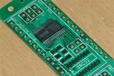
In order to use DIR9001 converter board, two logic need to be change on two ICs.
1. HC86 pin 5 short to pin 7 (pin 5 from 5V short to ground). This is to ensure the de-emphasis function works.
2. SM5842 pin 5 short to pin 10 (pin 5 from ground to +5V). This is to set the input mode of 5842 to 16 bit.
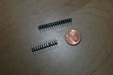
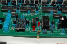
Since the trace on the main board is under a IC socket and cannot easily be cut or jump a wire. I use another layer of IC pins shown and cut one of the pin 5 and then solder a jumper wire to the required pins on the same row of IC pins. This IC pins are first inserted into the original IC socket and then the IC inserted on top of it (show on another photo).
Thus this change can be back ward convertible back to the 8412 receiver without soldering on the main board.
1. HC86 pin 5 short to pin 7 (pin 5 from 5V short to ground). This is to ensure the de-emphasis function works.
2. SM5842 pin 5 short to pin 10 (pin 5 from ground to +5V). This is to set the input mode of 5842 to 16 bit.
Since the trace on the main board is under a IC socket and cannot easily be cut or jump a wire. I use another layer of IC pins shown and cut one of the pin 5 and then solder a jumper wire to the required pins on the same row of IC pins. This IC pins are first inserted into the original IC socket and then the IC inserted on top of it (show on another photo).
Thus this change can be back ward convertible back to the 8412 receiver without soldering on the main board.
Attachments
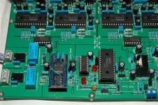
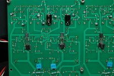
Dont forget to set the DIR9001 to 16 bit output mode and also 256Fs. Here is photo of the final main board with all the changes.
Note that the HC86 and 5842 is sitting on two layer of socket pins.
For those interested to do the upgrade, I can provide a converter board later but please give me an email first so that I know how many people are interested. I can provide either bare board or complete assembly of converter board.
Cheers.
Attachments
The next upgrade on the Jfet IV part is to reduce the input AC impedance so that the DAC can drive the current to 0V and Zero resistance to ground. This mean more linear and less distortion.
I have done this measurement as below to lower the impedance from 46.8 to 23.5 ohm.
1. Q3/Q8/Q13/Q18 use K170 x 1 give 46.8ohm
2. Q3/Q8/Q13/Q18 use K170 x 2 give 35.8ohm
3. Q3/Q8/Q13/Q18 use K170 x 3 give 29.3ohm
4. Q3/Q8/Q13/Q18 use K170 x 3 AND R3/R12/R23/R33 change from 33r to 13.2ohm (parallel a 22R resistor at the bottom) give only 23.5 ohm ac impedance at the jfet IV.
Conclusion:
The more Jfet in parallel will give lower impedance.
Increase the lower current source will also give lower impedance. Note that NP use 10mA for the mosfet.
But there is a limit on the max current can be set:
1. Idss of Q15.
2. Max power dissipated by Q15. Thus reducing the -20V supply is another way to increase the current source at the bottom.
3. The upper current source must also able to provide sufficient high current to drive the input and also the 1.5k resistor to ground.
4. Another idea is to use BJT current source to provide higher current source but that would not be labelled Jfet IV any more.
Thus diyer can try to see what the sound will change by playing with the value of R3/R12/R23/R33 or parallel more jfet to Q3/Q8/Q23/Q33.
Cheers
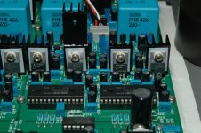
Next trial is to change all the 8 pcs PCM63 5V regulators from LM317/337 to LT1085/LT1033. Attached is the photo after change. A 22uF 10V polymer capacitor are also added to the output of the LT regulators at the bottom of the pcb. LT give more accurate voltage compare to normal LM regulators (range from 4.98 to 5.02V with 1% resistors 100R/300R).
A simple change is also able without changing the regulators is to add a 10uF capacitors from pin 1 of all regulator to the ground. It will also improve the noise rejection of all regulators according to the LM317/337 data sheet. Beware of the polarity of E-cap when doing the change.
Cheers.
A simple change is also able without changing the regulators is to add a 10uF capacitors from pin 1 of all regulator to the ground. It will also improve the noise rejection of all regulators according to the LM317/337 data sheet. Beware of the polarity of E-cap when doing the change.
Cheers.
Attachments
After few hour listening, I feel the sound is too tense. Thus I do the following changes.
1) Remove the tan cap 22uF on the +/-5V analogy supply of PCM63, change to a Panasonic FC cap 100uF 50V.
2) Put the 4 pcs 22uf Tan cap in parallel of the 300R resistor of the regulator ground resistors (analogy part).
3) Put 10uF 16V tan cap parallel to the 300R resistor of the regulator ground resistors (digital part).
The sound become more mellow and relax again.
Conclusion, the capacitor at the analogy 5V supply of PCM63 affact the sound a lot. Try to use the cap that suit your taste.
I go back to LM317/LM337 as the sound of LT regulators are too aggressive for me!
For you information, I am working on a Ver3 pcb and would like to know how many people are interested so that I know how many board to order later. The board will only be offer if the the result is better than ver2! It will have all the upgrades from Ver2.
Attached is a layout which is still changing everyday.
Spencer
- Home
- Vendor's Bazaar
- NP D1 DAC clone with enhancement