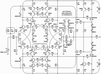
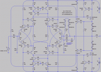
Next step is to equalize the currents in Q1/Q2/Q8/Q5 with those of Q3/Q19/Q24/Q6, change R1 R30 for 12ohm, add two more junctions to D8 D9 & D13 D14.About where the idea is at right now. Nothing final.
This will create a huge multidimensionnal Xquad, and could have unexpected results.
Equalizing those currents means using smaller R3,4,41,42, reducing input impedance.
Else replace with CCS that have to be VERY carefully matched to avoid any offset.
3 or four diodes in the X locks this sim to one rail, I don't know exactly why.
Transconductance and maybe global linearity improve, but local linearity gets
diode curvy in a way that doesn't seem particularly useful. Maybe bypassed
resistors wasn't such an awful suggestion... Excessive transconductance in
the in/out comparator seems to fight against (and harden) soft current limits.
What happens if I bypass Q3 Q19 with a resistor that shunts all but 1mA?
Then the voltage drop should exactly match Q1 Q2. Does it help? I suspect
not, but I'll be running a sim to be sure...
I think the match from left to right is far more important than any matching
up and down. I'm just keeping the collectors cascoded at a happy voltage,
not terribly concerned that up and down collectors see exactly the same.
Last edited:
Playing with positive reaction can be highly rewarding, as the cross-quad shows, but it is also difficult and risky.Equalizing those currents means using smaller R3,4,41,42, reducing input impedance.
Else replace with CCS that have to be VERY carefully matched to avoid any offset.
3 or four diodes in the X locks this sim to one rail, I don't know exactly why.
I have no idea about what's going on. I can figure out "with my guts" how a standard Xquad works, but in 3D it could take some more time.
Such a complex circuit certainly deserves an in-depth analysis. Not something you can carry out in an evening or two.Transconductance and maybe global linearity improve, but local linearity gets
diode curvy in a way that doesn't seem particularly useful. Maybe bypassed
resistors wasn't such an awful suggestion... Excessive transconductance in
the in/out comparator seems to fight against (and harden) soft current limits.
What happens if I bypass Q3 Q19 with a resistor that shunts all but 1mA?
Then the voltage drop should exactly match Q1 Q2. Does it help? I suspect
not, but I'll be running a sim to be sure...
But you were the one to open fire first by tying the collectors of Q1 and others to the bases of their opposite.
Maybe you did it because it was a convenient place to do so, from a DC perspective, but it also has dynamic implications, and part of the performance of your circuit is probably due to the resulting cross-quad effect.
Maximizing this effect without latching the whole thing up certainly is a worthwhile challenge
I've dumbed down absolute vertical symmetry, on the
premise that horizontal symmetry is more important.
Since I've got to92 devices, 10mA should be no prob.
Will require slightly less quiescent if using SMT duals...
Linearity within the X is key. No diodes, no caps.
Linearity worthy of the transconductance lost.
We slide voltage references from base to base that
do not have emitter curves, because those emitters
are held at 1mA by a strong local feedback. Resistors
that span the X thus also give us uncurved current.
Added transconductance can help us fix error of the
MOSFET. But comes at cost of curved error in the X,
and hardening of the soft current clipping. OLG 1000
with good linearity was already more than enough.
Sim with 4401 4403 I bought on the cheap: reveals
P and N thresholds that are slightly different, but
not having any symmetry issues effect except on
soft current clip. 6.5A vs 7A might want fixing...
You will need Bob Cordell's models, else delete both
MOSFETs and replace with LTSpice equivalents.
Attachments
Last edited:
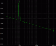
I have tried to simulate the circuit with a timestep of 1µs, but it shows instabilities, mainly at 25MHz:
Increase gate stopper resistors R37 and R38. I mentioned it erlier in the thread.
OK, looks pretty touchy: it has to be 33 ohm, and in addition, I had to add a 4.7R between the emitters of Q15 & Q16.Increase gate stopper resistors R37 and R38. I mentioned it erlier in the thread.
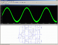
I've also disabled the clipper to look at the linearity.
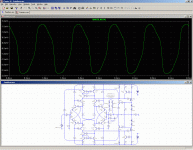
THD is 0.08%, but the error voltage has an unexpected look:
Attachments
- Status
- This old topic is closed. If you want to reopen this topic, contact a moderator using the "Report Post" button.
- Home
- Amplifiers
- Solid State
- Nothing to see here
