Eric said:Gengis:
I'm not sure that I trust those curves from the Seifert web page. I'd rather go by the numbers I received from the distributor. There is a curve for the 271 profile here but it does not match the data I got from my contact at RHM.
Given their chart for the 271, it looks to be rated at just under 0.25c/w for 100mm (4"). The data I got from the distributor (and posted earlier in this thread) indicates that a 6" section of 271 is rated at 0.22c/w. The chart shows somewhat less than 0.125c/w at this same 6" length.
The data from the charts seem to be overly optimisitc and could lead to some surprising results
Eric
The difference in the reported numbers could be due to the temperature difference between the heat sink and the surrounding air. The higher the temperature difference, the smaller the °C/W. I couldn't find the delta-T for which the Seifert charts were made, but it is likely to be significantly higher than 25°C.
Regarding the size of the Aleph 2 heat sinks. I think the commerical offerings had heat sinks designed so that the temperature increase was in the neighborhood of +25C. If you don't mind the higher temperature, running at +35C or even +40C is possible. I certainly do.

Jeremy
Pass DIY Addict
Joined 2000
Paid Member
Heatsink profile KL-271 appears to have more fins per inch of the same shape than KL-273. (17.7mm vs 22mm spacing). For free air convection, I do not believe there is any air flow advantages to the wider 22mm spacing used on KL-273. Does anyone have a textbook showing advantages between 22mm vs. 17.7mm for free convention?
I think that as long as the bottom of the heatsink has a 1" or so gap above the floor/shelf to start-up a chimmey flow, profile KL-271 would have lower C/watt for the same area than KL-273 because it has more fin area.
I think that as long as the bottom of the heatsink has a 1" or so gap above the floor/shelf to start-up a chimmey flow, profile KL-271 would have lower C/watt for the same area than KL-273 because it has more fin area.
Pass DIY Addict
Joined 2000
Paid Member
Pricing for KL-271
Hi Guys,
I have some pricing for the KL-271 profile, though the prices don't drop off for larger quantities as fast as I had hoped they would
KL-271 8" (203mm) 0.18c/w, black anodized, 5.6 kg each.
10 pc. min. $ 62.67 each
50 pcs. 59.19 each
100 pcs. 56.37 each
I hope to have pricing for the KL-273 profile by this afternoon. Also, I'll be away and not able to check in on the thread from Friday through Monday, I'll return on Tuesday.
Eric
Thanks gengis,
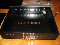
I really like that chassis and I think that would reaaly make a great looking amp chassis. I can use my table saw and cut it down to 3.5" so that it will fit nicely on my chassis. So the mini A will work nicely with the heatsinks on the outside of that chassis?
I'm just wondering how to run to power wire to the on/off switch without interfering with the amp and dc voltages. Any suggestions on how to run the power wire?
Thanks,
Josh
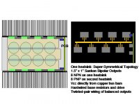
Example of KL-271 extrusion 8" x 12" heatsink with 8 bipolar transistors. The 8" height seems cost optimum for heat spreading, as a higher heatsink would have more limited heat conduction to the extreme perimeter. Naturally, a 12" high heatsink would have greater heat removal capability, but not as cost effective as a longer heatsink with larger horizontal separation between the transistors.
Currently considering one PCB for super-symmetrical amplifier and then hardwiring the bipolar output transistors on the heatsinks. The collectors would be directly connected to copper bus bars on the capacitors. Twisted pair wiring would be used between each bridged output transtor pair, and run to a common output connector where the emitter resistors would be summed, and the feedback wires run back to the PCB.
Any experience with trade-offs in bandwidth and distortion between hard wired outputs on the heatsink vs. a second PCB for the outputs?
Attachments
edjosh23,
I am not following what your question stated? A sketch would be easier to understand.
LineSource,
Which Sanken output devicesar you considering?
Ampslab uses the hardwire approach for their higher output boards.
I am currently looking for plans that utilized Sanken 2SC2922 and 2SA1216, that can put out at least 150W@8ohms.
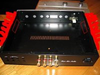
Here is a quick little change to th picture in Paint.
I made the heatsinks on the side in red so that they are easier to see. And inside are red squares, these are the aleph boards mounted on the side of the chassis.
Will this work? The Heatsinks will be bolted tightly to the side pannels of the chassis and I'm hoping that the heat will spread from the site pannels of the chassis to the heatsinks.
If I can (I'mm find out when I order it) I could take off the side pannels and use L brackets to replace the side pannels with the heatinks and the boards can be bolted directly onto the heatsink, but I'm not sure if that will work out or not depending on how the top of the chassis mounts on.
Thanks,
Josh
Attachments
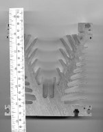
edjosh23 It is critical to mount transistors directly to the heatsink or you may lose up to 50% of the thermal conduction capacity, especially if your chassis is steel. A thermal text book or white paper from a heatsink company webpage will explain how much gaps affect conduction. The heatsink profiles the group is looking at are ~3" deep fins.
gengis I selected the lower power and lower max voltage Sanken 2SC2921Y and 2SA1215Y matched transistors because they have a higher 50Mhz ft, hfe >90, and my voltages are low enough to always keep the outputs in the safe operating area.
gengis I selected the lower power and lower max voltage Sanken 2SC2921Y and 2SA1215Y matched transistors because they have a higher 50Mhz ft, hfe >90, and my voltages are low enough to always keep the outputs in the safe operating area.
edjosh23,
Agree w/Linesource, mount the output directly on the heatsink.
The base of the heasink is more than 1/2" thick, you should be able to tap the base with #6-32 or #8-32 UNC.
For the top, mill a 3/8" wide x thickness of your top piece and tap #6-32 UNC again and use button head screws. That is if you have access to a milling machine. OTherwise, just bolt the top of the heatsink to the bottom of the fins.
- Status
- This old topic is closed. If you want to reopen this topic, contact a moderator using the "Report Post" button.
- Home
- Group Buys
- North America Heat Sink Group Purchase