Bernhard said:...the dynamics picture, does it show a low level (-67dB) 1 kHz sine ?
Yep, I used lower value gain resistors in the I/V stage than specified by the designer - what I had around - so the voltage out is a tad bit low (7dB lower than the sound card input level - I guess around 1V) but I won't change them now as both measurements and sound (on either CDP transport or soundcard) are spectacular.
I wouldn't pay that much attention to the freq graph, those values do not correlate with the sound quality;
I also guess that the soundcard also uses 24 bit internal for recording no matter what the output bitrate in order to improve the accuracy.
Regarding the DAC itself, I have to close the box, put a lock on it and throw away the key in case I get the tinkering itch - it's a finished item from this POV


Terry Demol said:
The AD1892 will impose a digital brickwall filter even when
resampling at 1:1, such is the nature of how ASRC's work.
The idea of 0 x OS is to get rid of brickwall filter.
Cheers,
Terry
Well, I hope I get it right, as far I as I understand it:
The AD1892 is the SPDIF receiver chip, the 1:1 resampling (recklocking) here would be needed to insure that the DAC is not keen at all on source jitter and uses it's own low jitter master clock - I tested this by accident - at first my SPDIF cable had the ground connection broken and the thingie stilll sounded pretty good. I had some reserves too on this, but the AD1892 specs + the very low jitter clock are good enough to ensure that the 1:1 resampling does not degrade the sound at all - see the measurements.
So the AD1892 spits out plain 1x44.1kHz I2S (which should be in 90% of the cases better than directly derived from the incoming jittery SPDIF/TTL signal) to the AD1865 dac; AD1865 I out and the I/V stage have no filtering of their own, just a miller comp cap in the I/V stage to decrease its bandwith to 1-2MHz and prevent self oscillation as the components used here will happily go to around 40Mhz and pick up any RF present in the area.
Hope I did not make any mistakes, I have only a MT degree (Master Tinkerer)
lucpes said:
Yep, I used lower value gain resistors in the I/V stage than specified by the designer - what I had around - so the voltage out is a tad bit low (7dB lower than the sound card input level - I guess around 1V) but I won't change them now as both measurements and sound (on either CDP transport or soundcard) are spectacular.
The thd graph shows -10 dB input level and the dynamics graph -67 dB input level,
so is it a low level DIGITAL signal in the dynamics graph ?
Or what does the dynamics graph show ?
Yep, in the dynamics graph there's a low level digital signal.
THD: 1kHz -3dB 'digital'
dynamics: 1kHz -60dB digital
IMD: -4dB 60Hz and -17dB 7000hz
The DAC's analog out at 0dB digital in is 7dB lower than the 0dB volume of the soundcard's line in, and all the graphs show the soundcard SPDIF->DAC->DAC's (analog) out->soundcard line in chain.
THD: 1kHz -3dB 'digital'
dynamics: 1kHz -60dB digital
IMD: -4dB 60Hz and -17dB 7000hz
The DAC's analog out at 0dB digital in is 7dB lower than the 0dB volume of the soundcard's line in, and all the graphs show the soundcard SPDIF->DAC->DAC's (analog) out->soundcard line in chain.
I really don't think that for a -60dB signal a -110dB harmonic is that bad. We're getting into thermal or resistor noise issues in this range, not to mention that I used a $100 soundcard to test with its inherent deficiencies
Here's a PDF regarding some basic concept of measurements for an older version the program used (RMAA 5.3 - http://audio.rightmark.org/). The basic concepts stayed the same, but the frequencies/amplitudes are a bit changed in new version.
Don't know about what you want to say by 'good dithered' signal... I'm not that technical, and I'm not the one who designed the DAC, just a happy customer...
Attachments
lucpes said:I really don't think that for a -60dB signal a -110dB harmonic is that bad.
Don't know about what you want to say by 'good dithered' signal... I'm not that technical, and I'm not the one who designed the DAC, just a happy customer...
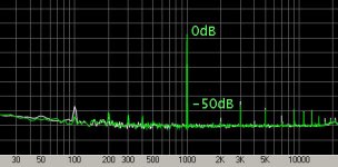
The -110dB is absolute scale, the signal is -60dB also absolte scale, so harmonics are -50dB.
Just shift the signal to 0 d<B and the harmonics by the same. They will be at -50 dB absolute scale.
That's really not true, as you can see in the THD graph (-3dB FS digital sine and resulting noise/harmonics);
There are lots of co-acting factors that result different harmonic spectrae when using 0dB FS or -60dB FS signals on every audio equipment one may wish to test which I won't bother to cover in this particular thread.
Based on your reasoning one would test a piece of equipment with a -90dB FS sine and conclude that a device has only 15dB of dynamic range if the most proeminent harmonic is -105dB FS
Bernhard said:DAC distortion gets worse with smaller signals.
Exactly my point
, and ~-110dB for most proeminent harmonic is very good (>90dB dynamic range) for a -60dB 1k sine.lucpes said:
Exactly my point
For your -60dB signal dynamics are 60dB, harmonics start at -50dB.
Attachments
@Bernhard:
Ok, I give up, you're right, in the pic the harmonics are <50dB lower than the signal.
1) the theoretical max dynamic range of a 0dB FS digital (16-bit signal) is ~96dB. 108 dB can be achieved when properly dithering the signal.
2) The digital signal in question was -60dB FS in reference to 0dB FS; by DIGITALLY ATTENUATING the volume to -60dB FS about 10bits (of information) are lost;
3) it's obvious that a much lower dynamic range/noise/harmonics (theoretically in the ~40dB range) for this particular digital signal that uses only 6 bits (and you may call it 0dB if you wish) should show up in both theory and practice on the test in question.
4) Keep the REFERENCE to 0dB FS digital and don't shift the graphs up&down unless you're really looking for a 6 bit DAC instead of a 16 bit one.
5) Point taken if you look for a 6 bit DAC...
Now, can you tell me which one of my points is flawed besides 5?
lucpes said:
Well, I hope I get it right, as far I as I understand it:
The AD1892 is the SPDIF receiver chip, the 1:1 resampling (recklocking) here would be needed to insure that the DAC is not keen at all on source jitter and uses it's own low jitter master clock - I tested this by accident - at first my SPDIF cable had the ground connection broken and the thingie stilll sounded pretty good. I had some reserves too on this, but the AD1892 specs + the very low jitter clock are good enough to ensure that the 1:1 resampling does not degrade the sound at all - see the measurements.
So the AD1892 spits out plain 1x44.1kHz I2S (which should be in 90% of the cases better than directly derived from the incoming jittery SPDIF/TTL signal) to the AD1865 dac; AD1865 I out and the I/V stage have no filtering of their own, just a miller comp cap in the I/V stage to decrease its bandwith to 1-2MHz and prevent self oscillation as the components used here will happily go to around 40Mhz and pick up any RF present in the area.
Hope I did not make any mistakes, I have only a MT degree (Master Tinkerer)
I will try to clarify, it seems you are missing the point.
The whole idea of a 0 x OS DAC is to get rid of the digital brickwall
filter. This DAC does not eliminate the brickwall filter because the
AD1892 has one. The AD1892 is Asynchronous and so must re-
calculate all incoming samples referenced to another clock source
than which is derived from the SPDIF data stream.
In the process of recalculating those samples it a) attenuates
sidebands caused from jitter, b) applies a brickwall filter.
If you want to use an ASRC the AD1896 is far superior to the
AD1892. If you want a digital filterless DAC then the AD1892 must
be used as a receiver only in bypass mode (if it has one) and as
such it will have no jitter rejection.
The best approach to this whole mess is TI DIR1703 or CS8414
receiver chip, then feed the clock signal into Guido Tents XO-DAC
PLL board, then feed your favourite DAC with NO digital filter.
I prefer TDA1541A S1/2, others here prefer TDA1543 and some
the AD chip.
For I-V go for the 0 feedback grounded base stage approach
as fisrt suggested by Jocko Homo.
The I-V in the DAC you mention IMO will not be as good as
the ones discussed elsewhere here.
Another simple approach is just a simple R I-V with a single
high gm tube such as 6C45, 3A167m or WE437A. These also
sound very very good.
Good luck
Terry
lucpes said:
Now, can you tell me which one of my points is flawed besides 5?
What I try to find out is, if >16bit dac chips are better at -60dB.
I have only 16 and 18 bit chips to compare for myself and it doesn't look like 18bit is better.
The best chips I found are 16bit with all harmonics below -60dB. It is PCM56 without selection stamp.
J and K selection I have are much worse, which I don't understand, except I have a theory:
Chips are selected after manufacturing and will change performance after "burn in" when they are used for years.
Most of my tested chips are from CD players.
I use a preamp, so -60dB signal is 0dB on my analyzer
Non Os makes distortion worse and the quality of your -60dB signal is unknown, so it is impossible to compare your results to mine.
Hi Terry Demol,
I don;t understand your last post. A (oversampling) brickwall filter must use a higher sampling rate to function. If the AD1892 is working on a Non Oversampling Sample rate (44.1KHz /ch) , how can it function as a brickwall, or is it functioning at a higher sample rate?
Cheers,
Thijs Schrama
I don;t understand your last post. A (oversampling) brickwall filter must use a higher sampling rate to function. If the AD1892 is working on a Non Oversampling Sample rate (44.1KHz /ch) , how can it function as a brickwall, or is it functioning at a higher sample rate?
Cheers,
Thijs Schrama
Konnichiwa,
I am not Terry, but to cut this short, in principle the operation of a ASRC (Asyncronous Sample Rate Converter) can be viewed as operating a oversampling digital filter with a very high oversampling factor followed by a downsampler, the downsampling ratio of which is adjustable.
That is not how it REALLY works, but the output response is in effect the same.
So, as long as the ASRC part of either the various AD parts or of the CS8420 is active, EVEN with an output sample rate that is notionally identical to the input one OR INDEED SYNCRONISED to the input sample rate you have a digital filter in the circuit.
That said, on some recordings I prefer the sound of the Ack!dAck (no oversampling, no "anti-sinc" filter) with a signal upsampled via CS8420 to 96KHz, on others not. At the time when the same signal goes through the Pacific Microsonics PDM200 HDCD Filter and PCM1704 DAC's (passive I'V, Tube output stage) I reliebaly prefer the 96KHz upsampling OFF....
Go figger.
Sayonara
tschrama said:Hi Terry Demol,
I don't understand your last post. A (oversampling) brickwall filter must use a higher sampling rate to function. If the AD1892 is working on a Non Oversampling Sample rate (44.1KHz /ch) , how can it function as a brickwall, or is it functioning at a higher sample rate?
I am not Terry, but to cut this short, in principle the operation of a ASRC (Asyncronous Sample Rate Converter) can be viewed as operating a oversampling digital filter with a very high oversampling factor followed by a downsampler, the downsampling ratio of which is adjustable.
That is not how it REALLY works, but the output response is in effect the same.
So, as long as the ASRC part of either the various AD parts or of the CS8420 is active, EVEN with an output sample rate that is notionally identical to the input one OR INDEED SYNCRONISED to the input sample rate you have a digital filter in the circuit.
That said, on some recordings I prefer the sound of the Ack!dAck (no oversampling, no "anti-sinc" filter) with a signal upsampled via CS8420 to 96KHz, on others not. At the time when the same signal goes through the Pacific Microsonics PDM200 HDCD Filter and PCM1704 DAC's (passive I'V, Tube output stage) I reliebaly prefer the 96KHz upsampling OFF....
Go figger.
Sayonara
tschrama said:Hi Terry Demol,
I don;t understand your last post. A (oversampling) brickwall filter must use a higher sampling rate to function. If the AD1892 is working on a Non Oversampling Sample rate (44.1KHz /ch) , how can it function as a brickwall, or is it functioning at a higher sample rate?
Cheers,
Thijs Schrama
Kuei Yang Wang said:Konnichiwa,
I am not Terry, but to cut this short, in principle the operation of a ASRC (Asyncronous Sample Rate Converter) can be viewed as operating a oversampling digital filter with a very high oversampling factor followed by a downsampler, the downsampling ratio of which is adjustable.
That is not how it REALLY works, but the output response is in effect the same.
So, as long as the ASRC part of either the various AD parts or of the CS8420 is active, EVEN with an output sample rate that is notionally identical to the input one OR INDEED SYNCRONISED to the input sample rate you have a digital filter in the circuit.
That said, on some recordings I prefer the sound of the Ack!dAck (no oversampling, no "anti-sinc" filter) with a signal upsampled via CS8420 to 96KHz, on others not. At the time when the same signal goes through the Pacific Microsonics PDM200 HDCD Filter and PCM1704 DAC's (passive I'V, Tube output stage) I reliebaly prefer the 96KHz upsampling OFF....
Go figger.
Sayonara
We may all be wrong.

On the AD1892 data sheet page 21 it
states that:
" Unlike the AD1890/91/93, the AD1892's rate converter does not
include automatic input frequency band limiting, which places
constraints on artifact free down sampling."
However further down same page it states
"The AD1892 ASRC performs 128 times interpolation, low pass
filtering, and resampling at the Mclck/512 (ie FS out) rate."
Based on the usual ASRC architecture, what Kuei says is right.
However there seems to be contradiction in the data sheet
statements.
As to what the 1892 actually sounds like, I would put my money
on the AD1896 as it has better linearity, DR and also very good
attenuation of jitter induced distortion.
Cheers,
Terry
Konnichiwa,
But we ain't....!!!!

It's worth quoting the whole thing, as this contains the answer.....
"Asynchronous Sample Rate Converter
The AD1892 uses a different Asynchronous Sample Rate
Conversion (ASRC) algorithm than the AD1890/AD1891/
AD1893. The upsampling range is much wider (1:5, from
10 kHz to 48 kHz continuous), but the downsampling range is
more constrained (48 kHz down to 44.1 kHz, without significant
artifacts). Unlike the AD1890/AD1891/AD1893, the AD1892’s
rate converter does not include automatic input frequency bandlimiting, which places constraints on artifact-free downsampling.
Program material sampled at 48 kHz can theoretically have
frequency content up to 24 kHz; when this is downsampled to
44.1 kHz, there can be aliased spectral energy from 20.1 kHz to
24.1 kHz, which is not fully attenuated by the AD1892’s digital
filter. For example, a full-scale 24 kHz signal would be attenuated
by –6 dB when resampled to 44.1 kHz.
The AD1892 ASRC performs 128 times interpolation, low-pass
filtering, and resampling (decimation) at the MCLK/512 (i.e.,
FSOUT) rate. The digital filter passband ripple is ±0.015 dB, and
the transition band extends from 20 kHz to 24.1 kHz. The
stopband attenuation is 120 dB."
So, what is said here is simply that on downsampling thge Digital Filter is not "good". But the ASRC is always there and it is always a digital filter.
Even more interesting is this bit:
(Page 18)
"ASRC Bypass Mode
By setting bit D0 HI in Control Register 1, the AD1892 will be
placed in “bypass mode,” where the received biphase-mark
encoded data is transmitted out of serial output interface without
any sample rate conversion applied. This mode may be
useful in applications where the audio data is not simple PCM
information; for example, the data may be compressed using the
MPEG or Dolby AC-3 compression standards. In this mode, the
output interface runs in master mode (LRCLK and BCLK are
outputs), and all three output format modes are available (leftjustified,
I2S-justified and right-justified). In bypass mode, without
an external PLL, jitter may be as high as one MCLK period."
So what this tells us is that the ONLY mechanism to reject ANY jitter is in the ASRC.
Unlike the Cirrus Logic parts that have a PLL (which also can be tweaked to have after "lock" a very SLOW rate of change by using a relais to switch in a large value capacitor attached via a high[ish] value resistor prior to lock), the jitter afte rthe receiver is whatever the source produced, plus a healty additional +/-1MCLK or 44nS (44000pS!!!!).
Now the ASRC is called upon to eliminate these 44,000pS jitter after the receiver. Am I the only one to feel that this may be a less than ideal solution?


Never mind the presence of a Digital filter, this filthy thing has build in a huge jitter mechanism which is hidden doe steady state measurements more or less well below the digital filter design (it still degrades the dynamic range of a 20Bit 20KHz signal to only 103db from the theoretical > 120db though), but what with music?
I would put my money on a CS8412/14 with 2-Speed PLL implementation as being massively superior and very easy to implement.
Given the 3000uS maximum group delay I would think a simple R256 Sample RAM buffer with DDS synthesized clock would be drastically superior without requiring the data to be altered.
The AD1892 strikes me as one of the typhical modern "Audio" engineering. Probably bets avoided like the plague.
Sayonara
Terry Demol said:We may all be wrong.
But we ain't....!!!!
Terry Demol said:On the AD1892 data sheet page 21 it
states that:
It's worth quoting the whole thing, as this contains the answer.....
"Asynchronous Sample Rate Converter
The AD1892 uses a different Asynchronous Sample Rate
Conversion (ASRC) algorithm than the AD1890/AD1891/
AD1893. The upsampling range is much wider (1:5, from
10 kHz to 48 kHz continuous), but the downsampling range is
more constrained (48 kHz down to 44.1 kHz, without significant
artifacts). Unlike the AD1890/AD1891/AD1893, the AD1892’s
rate converter does not include automatic input frequency bandlimiting, which places constraints on artifact-free downsampling.
Program material sampled at 48 kHz can theoretically have
frequency content up to 24 kHz; when this is downsampled to
44.1 kHz, there can be aliased spectral energy from 20.1 kHz to
24.1 kHz, which is not fully attenuated by the AD1892’s digital
filter. For example, a full-scale 24 kHz signal would be attenuated
by –6 dB when resampled to 44.1 kHz.
The AD1892 ASRC performs 128 times interpolation, low-pass
filtering, and resampling (decimation) at the MCLK/512 (i.e.,
FSOUT) rate. The digital filter passband ripple is ±0.015 dB, and
the transition band extends from 20 kHz to 24.1 kHz. The
stopband attenuation is 120 dB."
So, what is said here is simply that on downsampling thge Digital Filter is not "good". But the ASRC is always there and it is always a digital filter.
Even more interesting is this bit:
(Page 18)
"ASRC Bypass Mode
By setting bit D0 HI in Control Register 1, the AD1892 will be
placed in “bypass mode,” where the received biphase-mark
encoded data is transmitted out of serial output interface without
any sample rate conversion applied. This mode may be
useful in applications where the audio data is not simple PCM
information; for example, the data may be compressed using the
MPEG or Dolby AC-3 compression standards. In this mode, the
output interface runs in master mode (LRCLK and BCLK are
outputs), and all three output format modes are available (leftjustified,
I2S-justified and right-justified). In bypass mode, without
an external PLL, jitter may be as high as one MCLK period."
So what this tells us is that the ONLY mechanism to reject ANY jitter is in the ASRC.
Unlike the Cirrus Logic parts that have a PLL (which also can be tweaked to have after "lock" a very SLOW rate of change by using a relais to switch in a large value capacitor attached via a high[ish] value resistor prior to lock), the jitter afte rthe receiver is whatever the source produced, plus a healty additional +/-1MCLK or 44nS (44000pS!!!!).
Now the ASRC is called upon to eliminate these 44,000pS jitter after the receiver. Am I the only one to feel that this may be a less than ideal solution?
Never mind the presence of a Digital filter, this filthy thing has build in a huge jitter mechanism which is hidden doe steady state measurements more or less well below the digital filter design (it still degrades the dynamic range of a 20Bit 20KHz signal to only 103db from the theoretical > 120db though), but what with music?
Terry Demol said:As to what the 1892 actually sounds like, I would put my money on the AD1896 as it has better linearity, DR and also very good attenuation of jitter induced distortion.
I would put my money on a CS8412/14 with 2-Speed PLL implementation as being massively superior and very easy to implement.
Given the 3000uS maximum group delay I would think a simple R256 Sample RAM buffer with DDS synthesized clock would be drastically superior without requiring the data to be altered.
The AD1892 strikes me as one of the typhical modern "Audio" engineering. Probably bets avoided like the plague.
Sayonara
- Status
- This old topic is closed. If you want to reopen this topic, contact a moderator using the "Report Post" button.
- Home
- Source & Line
- Digital Source
- Non-Oversampling DAC