I've been working towards building some new big speakers for my kitchen/dining room, a fairly over-the-top two way line array using 4" SB midbass drivers and 3/4" Vifa dome tweeters.
As part of that development, I've been working on a very small transmission line for the 4" midbass units to provide some bass reinforcement that's in a form factor that can be stacked vertically to create a line array - that means the height of each unit (the noiseUnit) has to be barely bigger than the midbass diameter, but the baffle width and speaker depth is less important.
After a few iterations I came up with a 20cm x 12.5cm x 25cm brick that encompasses a low-CSA 1.06m long tapering transmission line. The enclosure is shown at http://www.diyaudio.com/forums/full...ng-40-hz-compact-enclosure-3.html#post5128543.
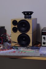
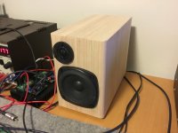
So after that work I had a pair of little MDF prototypes on my desk. I thought that rather than chuck them out I'd tip them on their sides to make some speakers for my desktop, as they were pretty-much exactly what I wanted in PC speakers.
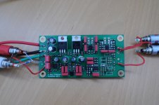
In order to make them useable I needed to knock together an equaliser and crossover, as much of the work I'd done previously was using my miniDSP. I also wanted a crossover/equaliser for my Ariels, which have similar needs, so I figured I'd make one PCB that would serve both uses.
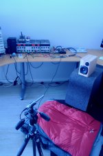
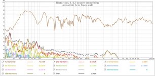
While waiting for PCBs to arrive I finished off my prototype enclosures with Tassie Oak veneer cut on my shiny new bandsaw. Midbass units are SB12PFC25-4 4" 4 Ohm plastic framed, paper cone drivers. These are a pretty basic driver, with no copper in the motor, and that's evident in distortion plots. They have lots of travel though, so are able to work well equalised to generate bass. I cross over at 3.4 KHz with a 4 pole Butterworth filter, using a straightforward Sallen-Key architecture, to a Vifa NE19VTS-04 3/4" dome tweeter to provide the treble. I've included about 40us of delay with a 2-stage all-pass filter to get the time alignment sorted at crossover.
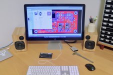
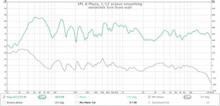
Last night I populated the crossover PCB and did some measurements, and I'm pretty happy. For cheapy, tiny speakers they sound really good. The bass is a little shy in the posted plots of the reality in-situ, as I get a fair bit of gain by placing them near the wall due to the rear-facing vent.
As part of that development, I've been working on a very small transmission line for the 4" midbass units to provide some bass reinforcement that's in a form factor that can be stacked vertically to create a line array - that means the height of each unit (the noiseUnit) has to be barely bigger than the midbass diameter, but the baffle width and speaker depth is less important.
After a few iterations I came up with a 20cm x 12.5cm x 25cm brick that encompasses a low-CSA 1.06m long tapering transmission line. The enclosure is shown at http://www.diyaudio.com/forums/full...ng-40-hz-compact-enclosure-3.html#post5128543.
So after that work I had a pair of little MDF prototypes on my desk. I thought that rather than chuck them out I'd tip them on their sides to make some speakers for my desktop, as they were pretty-much exactly what I wanted in PC speakers.
In order to make them useable I needed to knock together an equaliser and crossover, as much of the work I'd done previously was using my miniDSP. I also wanted a crossover/equaliser for my Ariels, which have similar needs, so I figured I'd make one PCB that would serve both uses.
While waiting for PCBs to arrive I finished off my prototype enclosures with Tassie Oak veneer cut on my shiny new bandsaw. Midbass units are SB12PFC25-4 4" 4 Ohm plastic framed, paper cone drivers. These are a pretty basic driver, with no copper in the motor, and that's evident in distortion plots. They have lots of travel though, so are able to work well equalised to generate bass. I cross over at 3.4 KHz with a 4 pole Butterworth filter, using a straightforward Sallen-Key architecture, to a Vifa NE19VTS-04 3/4" dome tweeter to provide the treble. I've included about 40us of delay with a 2-stage all-pass filter to get the time alignment sorted at crossover.
Last night I populated the crossover PCB and did some measurements, and I'm pretty happy. For cheapy, tiny speakers they sound really good. The bass is a little shy in the posted plots of the reality in-situ, as I get a fair bit of gain by placing them near the wall due to the rear-facing vent.
Attachments
-
 DSC_4750.jpg163 KB · Views: 896
 -
 IMG_0305.jpg226.5 KB · Views: 885
 -
 DSC_4756.jpg258.4 KB · Views: 862
 -
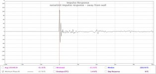 noiseUnit impulse response - away from wall.jpg73.9 KB · Views: 203
 -
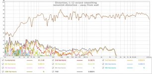 noiseUnit distortion - away from wall.jpg154.5 KB · Views: 266
 -
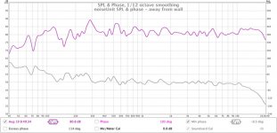 noiseUnit SPL and phase - away from wall.jpg80.6 KB · Views: 855
 -
 DSC_4766.jpg227.4 KB · Views: 857
Last edited:
Hi,
Well done ! They have a good phase plot & impulse too. You've made a very nice job of the veneering. Plus you designed the Xover & PCB as well")
Does NU on some components on the Xover = Not used ? If so it appears you didn't use the baffle step compensation, or HF Zobel ?
I would have put 1000uf caps on the bridge
Looks as if you have a fine selection of test gear etc, & you keep your workspace neat & tidy too
You should be extremely proud of your acheivements, i am ! I wish we had more clever girlies like you involved in audio etc. You're welcome round @ mine Anytime
Well done ! They have a good phase plot & impulse too. You've made a very nice job of the veneering. Plus you designed the Xover & PCB as well
Does NU on some components on the Xover = Not used ? If so it appears you didn't use the baffle step compensation, or HF Zobel ?
I would have put 1000uf caps on the bridge
Looks as if you have a fine selection of test gear etc, & you keep your workspace neat & tidy too
You should be extremely proud of your acheivements, i am ! I wish we had more clever girlies like you involved in audio etc. You're welcome round @ mine Anytime
Yes, NU means not used. The baffle step compensation is needed for my Ariels, but not for these ones. Initial testing of these speakers had a bit of a hole from 3-8 odd KHz. I initially removed that by using a tweeter step and a little extra gain, hence provision for these bits on the board. Mounting the tweeter flush with the baffle sorted that, so no need in the actual thing.
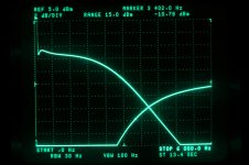
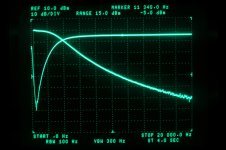
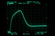
Measurements of the crossover/equaliser.
First a close-up of the woofer equaliser and DC block stage from DC-200Hz, then a zoomed out plot showing out to 20KHz, and finally a plot showing the high-pass and low-pass at the crossover region. No fancy log frequency scales on my spectrum analyser, I'm afraid.
First a close-up of the woofer equaliser and DC block stage from DC-200Hz, then a zoomed out plot showing out to 20KHz, and finally a plot showing the high-pass and low-pass at the crossover region. No fancy log frequency scales on my spectrum analyser, I'm afraid.
Attachments
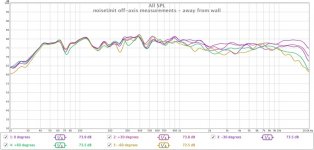
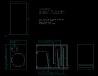
Attached off-axis response and drawings for the enclosure.
It would have been nice to cross to the tweeter a little earlier (I initially had the crossover set at 2500Hz) to improve dispersion, but the little Vifa NE19VTS just wasn't having it, even with the 4th order crossover filter.
It would have been nice to cross to the tweeter a little earlier (I initially had the crossover set at 2500Hz) to improve dispersion, but the little Vifa NE19VTS just wasn't having it, even with the 4th order crossover filter.
Attachments
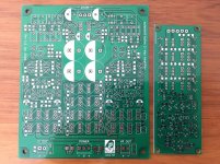
For completeness sake, here's the Gerbers for the crossover PCB. Please note that my prototype had a small stuff-up in the BSC and EQ stage (the eagle-eyed will note a bit of wire-wrap wire and a cut track). That's been fixed in these Gerbers.
And with that I hereby open-source this design. My only request is that people don't erase my name from the PCB. Go your hardest and have fun.
And with that I hereby open-source this design. My only request is that people don't erase my name from the PCB. Go your hardest and have fun.
Attachments
Nice results there Suzy,
I'm curious why the response doesn't dip more off axis at the higher frequencies. The published curves for the NE19VTS at 60 deg off axis are a good 10dB down at 10K, but your measurements are maybe half that.
That bass extension is wonderful. I've been struggling all weekend with my own project (FaitalPro 4FE35 in a transmission line) to get anything significant below 100Hz. But then again I'm not cheating with EQ
Does it sound as good as it looks?
Graham.

Two steps forward, one backward.
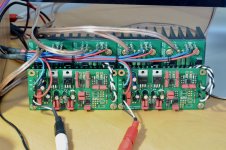
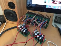
Firstly, I've been building amps, as this thing needs four. Attached a photo of four of my little 50W lateral MOSFET amps with a pair of crossover boards on top.
They're the steps forward. In there somewhere is digging out an old spool of lacing twine and remembering how to do lacing, for no better reason than I can and I like the look.
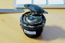
The second photo is the results of a leaky mica cap across one of the VAS transistors in one of the amps. It caused the VAS transistor to expire after a few hours, sending the output to the rail and causing the tweeter voicecoil to try it's best to leave and to get really smelly. These tweeters aren't very repairable - I ended up cutting it up to see what had happened.
Bugger! The kicker is that I'd recently removed the 20uf protection cap that I had in series with the tweeters, because with these 4 ohm tweeters it messes with the phase excessively.
Oh well, at least it's only a cheapy $45 tweeter, not an expensive one like in the Ariels.
Firstly, I've been building amps, as this thing needs four. Attached a photo of four of my little 50W lateral MOSFET amps with a pair of crossover boards on top.
They're the steps forward. In there somewhere is digging out an old spool of lacing twine and remembering how to do lacing, for no better reason than I can and I like the look.
The second photo is the results of a leaky mica cap across one of the VAS transistors in one of the amps. It caused the VAS transistor to expire after a few hours, sending the output to the rail and causing the tweeter voicecoil to try it's best to leave and to get really smelly. These tweeters aren't very repairable - I ended up cutting it up to see what had happened.
Bugger! The kicker is that I'd recently removed the 20uf protection cap that I had in series with the tweeters, because with these 4 ohm tweeters it messes with the phase excessively.
Oh well, at least it's only a cheapy $45 tweeter, not an expensive one like in the Ariels.
Attachments
New tweeter installed, and DC protection / anti thump circuit knocked together so it can't happen again.
The protection circuit is simply an adaptation of my usual anti-thump circuit. I have an NPN and PNP transistor monitoring a low-pass filtered version of what's coming out of the amps. if the voltage goes more than Vbe either positive or negative, one of the transistors turns on. The negative side has another transistor to invert the signal, then they're or-ed with two more transistors. The resulting signal simply resets the anti-thump.
If the DC voltage exceeds a few hundred millivolts the relay simply shuts off the speaker. Take the fault away and it turns back on after a few seconds.
Attachments
Last edited:
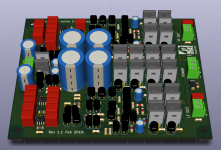
I've been playing with little (cheap) amplifiers based on BD179 & BD180 output drivers. That's prompted me to redesign the amps for the noiseUnit as a single integrated PCB, rather than the 50W MOSFET amp + active crossover + protection (4 PCBs per channel) circuit that I've been using.
The 50W MOSFET amps are overkill for these speakers - they're much better repurposed to bigger drivers. Instead I have a simple (just 100 transistors!) PCB with a 15W amp for the woofer, a 5W amp for the tweeter, and all the active crossover stuff, plus regulator circuitry for the crossover.
The amplifiers are my cascaded diamonds (see solid state forum), which should achieve <10 PPM THD up to clipping, and <5nV/sqrtHz input referred noise, so despite being small and built from cheap parts they're no slouches in terms of performance.
To try to preserve performance I've gone for better opamps for the crossover - OPA1612 input (1.1nV/sqrtHz) - $10 ea - and OPA1662 - $3 ea - for the filter functions. Input is differential to reject hum, but one side can be grounded to use single ended inputs.
The 12cm x 10cm PCB is basically the whole lot - add a +/-12VAC transformer and play music. It's not just applicable to these speakers either - with a few component substitutions in the crossover it should suit a reasonable range of small-medium 2 way speakers.
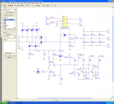
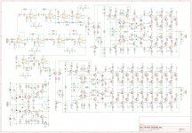
Attached schematic screen grab, screen grab of PCB layout, and zip file containing all the design files in KiCAD format, plus Gerbers for manufacture.
I'm awaiting the PCBs to build some real ones - when they arrive I'll post up the results.
The 50W MOSFET amps are overkill for these speakers - they're much better repurposed to bigger drivers. Instead I have a simple (just 100 transistors!) PCB with a 15W amp for the woofer, a 5W amp for the tweeter, and all the active crossover stuff, plus regulator circuitry for the crossover.
The amplifiers are my cascaded diamonds (see solid state forum), which should achieve <10 PPM THD up to clipping, and <5nV/sqrtHz input referred noise, so despite being small and built from cheap parts they're no slouches in terms of performance.
To try to preserve performance I've gone for better opamps for the crossover - OPA1612 input (1.1nV/sqrtHz) - $10 ea - and OPA1662 - $3 ea - for the filter functions. Input is differential to reject hum, but one side can be grounded to use single ended inputs.
The 12cm x 10cm PCB is basically the whole lot - add a +/-12VAC transformer and play music. It's not just applicable to these speakers either - with a few component substitutions in the crossover it should suit a reasonable range of small-medium 2 way speakers.
Attached schematic screen grab, screen grab of PCB layout, and zip file containing all the design files in KiCAD format, plus Gerbers for manufacture.
I'm awaiting the PCBs to build some real ones - when they arrive I'll post up the results.
Attachments
Last edited:
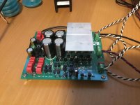
Here's the prototype mostly knocked together. I have no stock of OPA1662 or OPA1612 opamps, so I knocked it together with NE5532 opamps which I had to hand. Additionally I haven't populated all the output transistors for the LF amp (4 sets of six). I also went for 100Ω output stage bias resistors to reduce the quiescent current. This has a bit of a penalty on overall power before clipping - meaning I can manage about 12W with the LF stage and 6W with the HF stage before clipping.
One small gotcha - the bipolar input opamp at U3 has way to high Ib, resulting in a whopping 200mV offset by the LF amplifier output. I fixed this (40mV output offset) by substituting an OPA2132, which I have plenty of in stock. A different FET input opamp might be more appropriate in this spot.
So far it's working very well - the active filter response is to spec, 50Hz harmonics are really well suppressed, and it has no trouble whatsoever driving the noiseUnit drivers quite loud.
Attachments
- Status
- This old topic is closed. If you want to reopen this topic, contact a moderator using the "Report Post" button.
- Home
- Loudspeakers
- Multi-Way
- noiseUnit - transmission line computer speakers.