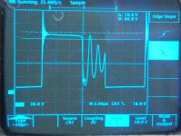
Here is the Vds waveform – without a snubber! Most of the ringing was caused by the setup, as I mentioned. Only a very minimal snubber is needed to tame the waveform – 4.7k//0.01uF worked for me, but I suspect this is not optimal; I didn’t bother to measure the leakage inductance of the final circuit for even better values. I could probably get away without one – the worst case spike magnitude is now well within the mosfet limits, but I will snubber anyway. With the above values, snubber dissipation is very low.
Attachments
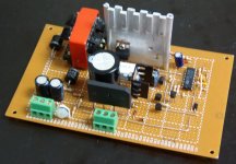
Finally, here is the completed circuit. I will not bother posting another schematic, there are very few changes:
1) I modified the feedback to fit the only potentiometer I had left, nothing functional changed.
2) Increased the soft-start capacitor C2 to 47uF to reduce stresses on turn-on. (I occasionally heard some transformer singing on start-up with 10uF… could have also set the current limit tighter, I guess).
3) Noise was tame enough I did not bother with D9 and … D9? [oops, schematic error again") ].
].
4) Increased R4 to 4.7k.
I’ve load tested the circuit with a 0.5A load for a while, all parts were cool to the touch afterwards. My only remaining problem is that I cannot test the full load of 3A for more than a few seconds – the dissipation would be over the limits of the resistors I have, even if they were heat-sinked properly. Any suggestions on a common lab or household item of some sort I could use to load 36V to around 3A? I thought of 40/60/100W light-bulbs, but I am worried about the off-state resistances I measured. I currently have 4 old soldering irons on a power bar, but this only loads to the 0.5A I mentioned previously.
If anyone is ever interested in actually building this piece of … excellent engineering … I can provide a final schematic and some more construction details (maybe even a proper PCB layout). Other than that, thank you all very much, you’ve all been an excellent help!
1) I modified the feedback to fit the only potentiometer I had left, nothing functional changed.
2) Increased the soft-start capacitor C2 to 47uF to reduce stresses on turn-on. (I occasionally heard some transformer singing on start-up with 10uF… could have also set the current limit tighter, I guess).
3) Noise was tame enough I did not bother with D9 and … D9? [oops, schematic error again
].4) Increased R4 to 4.7k.
I’ve load tested the circuit with a 0.5A load for a while, all parts were cool to the touch afterwards. My only remaining problem is that I cannot test the full load of 3A for more than a few seconds – the dissipation would be over the limits of the resistors I have, even if they were heat-sinked properly. Any suggestions on a common lab or household item of some sort I could use to load 36V to around 3A? I thought of 40/60/100W light-bulbs, but I am worried about the off-state resistances I measured. I currently have 4 old soldering irons on a power bar, but this only loads to the 0.5A I mentioned previously.
If anyone is ever interested in actually building this piece of … excellent engineering … I can provide a final schematic and some more construction details (maybe even a proper PCB layout). Other than that, thank you all very much, you’ve all been an excellent help!
Attachments
Ah, thank you for the idea! I wound up using an old hot plate that I found in the lab, it works nicely (cold resistance of around 20 ohms). I would love to try the MOSFET idea, although wouldn't BJT's make for a simpler (and more easily adjustable) constant current load? Either way, I have no spare heatsinks around, so it doesn't matter for me
Terran,
Nice work. What is the pri-sec winding ratio? If you were doing a single-ended output, you could re-do the power transformer section in a SEPIC topology (Single-Ended Primary Inductance Converter). This would allow the input voltage to be higher or lower than toe output. Not sure how this would play out with a bi-polar output, like your +/-18V. Just a thought..... I'm always thinking...........
Nice work.
What is the pri-sec winding ratio? If you were doing a single-ended output, you could re-do the power transformer section in a SEPIC topology (Single-Ended Primary Inductance Converter). This would allow the input voltage to be higher or lower than toe output. Not sure how this would play out with a bi-polar output, like your +/-18V. Just a thought..... I'm always thinking........... Thanks for the compliments everyone
I have been quite busy again... all the amps are working now, although I had to bias them for a higher quiescent current than expected to produce a sufficient minimum load.
Eva: The funny thing is that I have a huge stockpile of parts that I have not yet had shipped to my apartment, since I do not have the room. I know that I have a pile of the same power resistors somewhere in there (4 ohm, 25W, metal case... I think you can see a corner of one in one of my pictures). However, I will keep an eye out on ebay as you suggested, always happy to find some new bargains.
N-Channel: The primary-secondary ratio is 8:5/5, designed for a primary inductance of around 55uH. I had a look at the SEPIC topology as you suggested... turns out there is even an isolated version. I too am not certain on the details of obtaining a dual output, but if an isolated version is possible, then this should not be an issue. What are the usual component trouble areas when designing an off-line supply using this topology? That would be my next project (currently a scaled-up version of this supply). This would probably be some time in the future, though... I was in a hurry to finish this one, since I have a very narrow window for such projects. Later on, anything that's not finished tends to get shelved semi-permanently.
-=terran=- said:Thanks for the compliments everyone
.....N-Channel: ........ I had a look at the SEPIC topology as you suggested... turns out there is even an isolated version. I too am not certain on the details of obtaining a dual output, but if an isolated version is possible, then this should not be an issue. What are the usual component trouble areas when designing an off-line supply using this topology?.....
For the non-isolated topology, I would say the coupling capacitor from the first to the second winding (Don't go calling it a "primary" & "secondary", though, because some SEPICs do not magnetically couple the two windings) is the most critical component, and its working voltage should be the the sum of the absolute values of the input & output voltages.
- Status
- This old topic is closed. If you want to reopen this topic, contact a moderator using the "Report Post" button.
- Home
- Amplifiers
- Power Supplies
- Noise from TL494 Flyback supply