I fooled around with the RP some this weekend and it seems that the slight offset being displayed is just some type of bug when it is zoomed in at these low VHF frequencies. Next time I use it on HF, I'll see if it does it there. The counted frequency remains accurate. Also, it looks like the input channel to channel isolation on my RP is about 50 dB.
I also turned on the second, fixed, oscillator in that QRP labs VFO to evaluate it for a conversion oscillator. It's better than that other Si5351 based device, but that's not really saying much. The good news is that, unlike the other device, on this device when the fixed oscillator is turned off, it is actually off. The fixed output on mine is about -6 dBm and pretty nasty looking. Like the other, the crosstalk between fixed and tunable output is substantial.
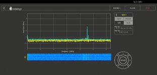
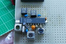
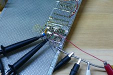
Pic 1 is the baseline, RX strip the same as last seen. The IF is showing a BCB station on 790 KHz, 5 KW input, single antenna, about 12 km from my house up at the lake. I'm down in the hills, but it still has a pretty good signal. The LO is high side at 45.790 MHz, receiving antenna is about 4 meters of wire tossed across the floor and clipped to the low pass input.
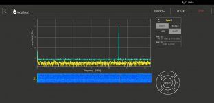
Second pic is the fixed oscillator turned on, and set to 34.3 MHz for down conversion to 10.7 MHz, but is not connected to anything. The bleed through to the main channel is substantial, and looks like it is degrading the reception, as the image of the BCB station is showing up at a low level.
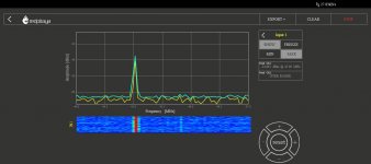
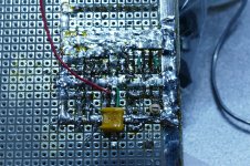
So, I reworked the IF some; the first mixer is now single ended and working directly into the two pole crystal filter. I added a second BF1105 amp and tail ended it with another crystal filter as its load. Third and fourth pics are the result, didn't add much additional gain, but much cleaner looking IF output. Fourth pic is just the clip lead as an antenna.
I'm running out of room, so I may have to use that fixed oscillator in the Si5351 if I want to add another conversion. Hopefully the two 45 MHz IF stages will be enough to try out the RP as an SDR receiver. When I figure out how to do that.
I also turned on the second, fixed, oscillator in that QRP labs VFO to evaluate it for a conversion oscillator. It's better than that other Si5351 based device, but that's not really saying much. The good news is that, unlike the other device, on this device when the fixed oscillator is turned off, it is actually off. The fixed output on mine is about -6 dBm and pretty nasty looking. Like the other, the crosstalk between fixed and tunable output is substantial.
Pic 1 is the baseline, RX strip the same as last seen. The IF is showing a BCB station on 790 KHz, 5 KW input, single antenna, about 12 km from my house up at the lake. I'm down in the hills, but it still has a pretty good signal. The LO is high side at 45.790 MHz, receiving antenna is about 4 meters of wire tossed across the floor and clipped to the low pass input.
Second pic is the fixed oscillator turned on, and set to 34.3 MHz for down conversion to 10.7 MHz, but is not connected to anything. The bleed through to the main channel is substantial, and looks like it is degrading the reception, as the image of the BCB station is showing up at a low level.
So, I reworked the IF some; the first mixer is now single ended and working directly into the two pole crystal filter. I added a second BF1105 amp and tail ended it with another crystal filter as its load. Third and fourth pics are the result, didn't add much additional gain, but much cleaner looking IF output. Fourth pic is just the clip lead as an antenna.
I'm running out of room, so I may have to use that fixed oscillator in the Si5351 if I want to add another conversion. Hopefully the two 45 MHz IF stages will be enough to try out the RP as an SDR receiver. When I figure out how to do that.
Attachments

Last edited:
... The board also has a complete IF strip including a RSSI (Received Signal Strength Indicator) capable of 90 db of dynamic range. ... To my surprise the SA605 chip is still available in SMD only, so if the 455 KHz filters are available, SMD would be OK, this still may be a valid project ...
George,
Did you play any with this chip for AM?
I bumped into this magazine article that claims to have used the RSSI output on the SA605 as a demodulated AM output. I probably have too much gain at 45 MHz right now for that; I would think driving the chip into limiting should be avoided, but it's easy enough to remove that last amp, or just put an attenuator ahead of the chip.
I just looked and the SA605 is still in stock at Mouser.
Attachments
Did you play any with this chip for AM?
Not recently, and not expressly for AM demod, but I did make AM sound come from the chip. I used the chip for a 45 MHz back end with a RFMD (now Quorvo) synthesizer / mixer chip in front of it. I also had a third board with several band pass filters and LNA's that never quite worked right, and was canabalized for parts.
I looked in my box of dead boards since sometimes I remember useless stuff from long in my past, but not what I had for dinner last night......sure enough, there it was. I built a test circuit back in 1989 using the new (at the time) Signetics SA 605 chip. The idea was to use the RSSI output for a DIY RF spectrum analyzer. If my 30 year old memories are correct there was more than enough dynamic range for a spectrum analyzer and the RSSI was fast enough for a pretty fast scan using a scope in XY mode for a display.
I can't find the original Signetics data sheet with the full explanation, but I believe that the RSSI output works by sensing the current drawn by each IF stage as it is pushed further into compression. Each stage has about 20 dB of dynamic range before it hard limits. This means that you want to drive it into the limiting area for proper AM detection. The RSSI will not do anything until the chip is driven hard enough for the last stage to begin compression, and it saturates when the first stage hits hard clipping. The output tracked within a couple dB over 60 or 70 dB of signal strength, plenty good enough for speech demod.
I know that I used this thing for listening to CB and a few local hams on HF AM. I never tried to do SSB demod, but I have heard that it is possible. I also used it to listen to FM cordless phones on 2.4 GHz. I never got the software right for the Windows based spectrum analyzer so all of it wound up in the big box of dead circuits. I still have this board, and the RFMD synth / mixer board, but the software for the synth was written for XP and used a com or printer port, don't remember for sure.
The SA605 stuff appears intact, maybe I'll hook a power supply to it and see what happens. Maybe it will still work after 30 years of life in the junk box??????
Attachments
So I fired up the 30 year old board and found it dead, no surprise there it's been living in the "dead circuits" box where I shop for unusual parts from my past.
A little poking around with a spectrum analyzer revealed no local oscillator. A little comparing the old board to the new schematic revealed a dead short across a capacitor in the tank circuit, not a shorted cap, but a well placed blob of solder. Who knows what I was doing with this board 30 years ago, but I probably wanted to inject an LO from a sig gen. I removed the blob, and the board is live.
AM detection via the RSSI pin does work. It works best in the -50 to -60 dbm input at 45 MHz range but the output amplitude and distortion remains usable from -30 to -100 dbm. The signal becomes clipped (expected) with input stronger than -30 dbm. A weird random distortion occurs at weak signal.
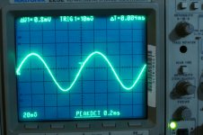
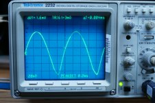
The first picture shows the output, about 750 mV P-P at -55 dbm and 80% AM. The THD increases a bit at 90% AM and the signal gets rather pointy on the bottom at 100% AM, second picture.
A little poking around with a spectrum analyzer revealed no local oscillator. A little comparing the old board to the new schematic revealed a dead short across a capacitor in the tank circuit, not a shorted cap, but a well placed blob of solder. Who knows what I was doing with this board 30 years ago, but I probably wanted to inject an LO from a sig gen. I removed the blob, and the board is live.
AM detection via the RSSI pin does work. It works best in the -50 to -60 dbm input at 45 MHz range but the output amplitude and distortion remains usable from -30 to -100 dbm. The signal becomes clipped (expected) with input stronger than -30 dbm. A weird random distortion occurs at weak signal.
The first picture shows the output, about 750 mV P-P at -55 dbm and 80% AM. The THD increases a bit at 90% AM and the signal gets rather pointy on the bottom at 100% AM, second picture.
Attachments
Last edited:
Thanks, George.
That is pretty amazing, it looks like the '605 could be very close to a single chip solution for a very simple general coverage broadcast receiver.
I don't want to upgrade this little board to an actual project and have it distract too much from the other thing; it would take pretty much complete rework to drop a 20 pin chip in since the DIP adapters have to install perpendicular to the long axis of the board, but ...
Since the datasheet for the '605 states it is an (improved) one chip combination of the '602 and '604, I looked, and sure enough the '604 is still in production in SMD form and available at Mouser. I looked on ebay and found some surplus DIP SA604 from a seller in Missouri, so I bought a couple of those this morning. I'll put a couple of '605's in my cart for my next order.
The '604 might work for me. I can keep my 45 MHz IF out for possible use with the RP as a starter SDR, and use the '604 for local demodulation. I'm guessing if you put carrier oscillator into the pin where the quad network normally goes, you get some form of product detection, so SSB/CW might also be feasible. The data for the '604 states it is good to 25 MHz; I'm guessing it will work at 45 MHz with reduced sensitivity, which would be fine since I already have decent gain at 45 MHz.
Not sure on AGC control. I'll have to think on that some. Current SA604 datasheet attached.
Attachments
The 605 seemed to have a sweet spot in the -55 dbm range, so it would make sense to set up an AGC to keep the chip's input in this range. This could be as simple as an opamp circuit that adjusts the gain on a Variable Gain Amp, or attenuator as to keep the average DC voltage on the RSSI output constant. A slow enough time constant will be needed to prevent cancellation of the audio output and chopping up CW, but fast enough to track out fading. This is why some high end receivers have a fast / slow stitch.
Every FM two way radio that Motorola made since the late 80's employed some kind of AGC, even though it is "theoretically" not needed with FM. All the modern FM stuff digitizes the IF in the 455 KHz to 2 MHz range and then adds some selectivity and demodulates in a DSP. The idea here is to optimize the RF / IF gain to keep the 16 bit converter in its sweet spot for dynamic range.
I know that I got a patent from work done in the late 80's involving variable intercept point LNA's which could shed current drain if the Bit Error Rate was above a threshold. This led to all sorts of BER VS current drain optimization work that carried over to cell phones.
When you are getting hit with a strong signal you engage an attenuator in front of the RX LNA to reduce intermodulation (yes the same stuff that make your HiFi sound bad). This was done in radios from the mid 80's on.
Simple Dumm Blonde idea, just flip the T/R switch into the transmit mode. The loss is about 20 dB, same as the fixed attenuator chip that got pulled out of the radio.
I spent countless hours driving around south Florida finding real world worse case test scenarios for two way radios. Around 199 to 2004 this was a "worse case" location for 800 MHz two way radios. This site was on the western edge of Broward county facing the Everglades swamp. There were 5 different sets of cell sites at this location all cranked up to (or above) the maximum ERP limit for cell site in order to offer some coverage in the swamp. This photo is the cover of a 40 page document outlining the issues and possible solutions to the fact that cops couldn't hear the dispatcher when they drove down this road.
The front of my white Mustang can be seen in right side of the picture. At first the cops thought I was up to no good, especially when I had a case full of radios set up on their frequencies (RX only). After a while they grew used to the Dumm Blonde dragging a spectrum analyzer, a car battery and an inverter around in a cow field.
This pales to the situation for UHF radios on the upper deck of the Miami Dolphins Football stadium. Here you are about a mile away from the Miami TV antenna farm where 14 stations operate 1 MEGAWATT transmitters in the UHF band. Fortunately most of the public safety in the area is at 700 or 800 MHz.
Attachments

Thanks, George.
That is pretty amazing, it looks like the '605 could be very close to a single chip solution for a very simple general coverage broadcast receiver.
I don't want to upgrade this little board to an actual project and have it distract too much from the other thing; it would take pretty much complete rework to drop a 20 pin chip in since the DIP adapters have to install perpendicular to the long axis of the board, but ...
Since the datasheet for the '605 states it is an (improved) one chip combination of the '602 and '604, I looked, and sure enough the '604 is still in production in SMD form and available at Mouser. I looked on ebay and found some surplus DIP SA604 from a seller in Missouri, so I bought a couple of those this morning. I'll put a couple of '605's in my cart for my next order.
The '604 might work for me. I can keep my 45 MHz IF out for possible use with the RP as a starter SDR, and use the '604 for local demodulation. I'm guessing if you put carrier oscillator into the pin where the quad network normally goes, you get some form of product detection, so SSB/CW might also be feasible. The data for the '604 states it is good to 25 MHz; I'm guessing it will work at 45 MHz with reduced sensitivity, which would be fine since I already have decent gain at 45 MHz.
Not sure on AGC control. I'll have to think on that some. Current SA604 datasheet attached.
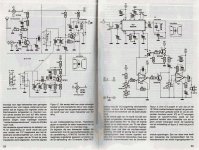
Very long ago I designed an AM-FM radio with the NE604. Sensitivity below 1uV and worked rather well. Circuit diagram attached.
Attachments
Thank you for scanning and posting that schematic, Aridace.
I got some SA604 in the mail today, but likely won't have much time to solder on the board before the weekend.
There are a couple of other chips that might work here: the interesting but really, really old LM373 ( I have a few left over from the first SSB rig) and the not nearly as old, but still obsolete, TDA1072. I was looking inside my Drake SW-1 and saw that was their choice for the second IF / detector. The SW-1 is 45 MHZ first IF, 455 KHz second IF, AM only. I ordered a couple of TDA1072, from a vendor in Dayton, possibly Drake surplus.
I guess ordering parts borders on turning it into a project.
Attachments
Interesting chips indeed and very useful because there's a functional internal diagram.Before I was able to design PLL demodulators that could provide better performance than for instance TBA 120 (FM) and TCA440 (AM) I used those according to the datasheet and that was rather good already, and far better than modern radios available for consumers here in Panama.
My plan to use 45 MHz 15 KHz filters for a receiver had to be shelved because the power company used the covid national house arrest to install digital controllers - resulting in a noise level of S9 +30 dB from ~100 KHz to 3 MHz. So back to the drawing board, 1st IF has to be at least 1 MHz wide, to allow true broadband noise processing (none of my existing RX's, including SDR, can). On the scope, I measured 0.25 Vpp from a wide-band open dipole, each leg 1.5m!
My plan to use 45 MHz 15 KHz filters for a receiver had to be shelved because the power company used the covid national house arrest to install digital controllers - resulting in a noise level of S9 +30 dB from ~100 KHz to 3 MHz. So back to the drawing board, 1st IF has to be at least 1 MHz wide, to allow true broadband noise processing (none of my existing RX's, including SDR, can). On the scope, I measured 0.25 Vpp from a wide-band open dipole, each leg 1.5m!
Since the SA604 RSSI output is set against 100K, can I just omit the 100K resistor on pin 5 and use 100K and 100 ohms, instead of 4.7M and 4.7K, on that JFET amp? Or is there some other reason for that combination? edit: is this to keep the JFET's bias from overriding the RSSI output voltage?
Last edited:
The RSSI output is (PNP) open collector so the resistor is required. The other output (pin6) has internal resistor of 55k so a high value of R5 in the circuit diagram is appropriate. The applied values were the best compromise to get comparable AM and FM audio output and useful squelch on both.
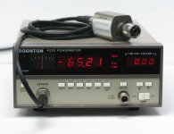
Just bought a Boonton Power Meter with calibrated Power Sensor, the thing can measure from 500 KHz up to 18GHz. Its just what I've been missing and needed to measure the output power from my own power amplifier an LNA designs. I wanted an HP meter, but they are a lot more expensive, specially the power sensor. This Boonton seems good enough for rock n roll
Attachments
Last edited:
")
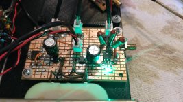
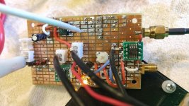
I added an XH connector for the SI5351 fixed output to the mainboard of the TX test jig. While I had the mainboard out, I beefed up the attenuator / dummy load to handle a bit more power in anticiption of the second iteration of the TX strip - probably something push pull, around 5 watts or so. I had a couple of clear LED's to indicate the regulators were working - these were so bright they would light up the whole darn room. I removed the LED on the 5 volt output, and changed the 12 volt LED to green. This is mildly less annoying.
I added an SA602 second mixer for down conversion. I wanted to use the HP IAM81008 chip here, but I didn't have any with me. So it was either JFET's, MOSFET's, or an SA602. Until I can add an AGC, I added a pot to set the IF gain. I don't think there is room for a 14 or 16 pin chip - they have to go perpendicular to the long axis of the board, and they're going to have to wait for the next iteration. Maybe a real companion general coverage receiver to the transceiver.
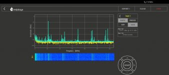
The screen shot is the 455 KHz second IF. I haven't decided what second IF I want to use, so for this screen shot there is no selectivity at the second IF. All of the trash is from turning on the fixed second output of the Si5351. The mixer may also be overloading a bit, or being overdriven by the second LO, or both - I haven't tinkered with it yet. I don't think there is room for a crystal conversion oscillator; that will also have to wait for a real receiver build.
Test conditions are the same - 5 KW single tower BCB station about 12 km from here; 3 or 4 meter wire antenna thrown on the floor, 45.790 MHz first LO, 44.545 MHz second LO, 455 Khz IF out.
I added an SA602 second mixer for down conversion. I wanted to use the HP IAM81008 chip here, but I didn't have any with me. So it was either JFET's, MOSFET's, or an SA602. Until I can add an AGC, I added a pot to set the IF gain. I don't think there is room for a 14 or 16 pin chip - they have to go perpendicular to the long axis of the board, and they're going to have to wait for the next iteration. Maybe a real companion general coverage receiver to the transceiver.
The screen shot is the 455 KHz second IF. I haven't decided what second IF I want to use, so for this screen shot there is no selectivity at the second IF. All of the trash is from turning on the fixed second output of the Si5351. The mixer may also be overloading a bit, or being overdriven by the second LO, or both - I haven't tinkered with it yet. I don't think there is room for a crystal conversion oscillator; that will also have to wait for a real receiver build.
Test conditions are the same - 5 KW single tower BCB station about 12 km from here; 3 or 4 meter wire antenna thrown on the floor, 45.790 MHz first LO, 44.545 MHz second LO, 455 Khz IF out.
Attachments
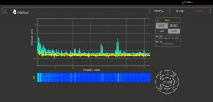
The second mixer is not being overloaded at the IF input. I reduced the 2nd LO drive some, and this made some marginal improvement at the 2nd IF output at the expense of some conversion gain. Since this isn't really a project, instead of making attenuators, I'm varying the drive the lazy way by adjusting the value of the LO coupling cap.
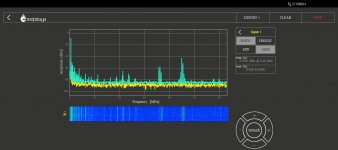
The first two pictures are with a 44.545 MHz 2nd LO. You can see the 2nd LO, the first IF, the LO, and I think the LO plus the 455 KHz 2nd IF all clustered around 45 MHz. I don't know what that stuff around 37 MHz is - some combinaton of Si5351 spurs and cross talk between the Si5351 outputs, I guess.
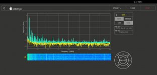
The third pic is with a 34.3 MHz 2nd LO for 10.7 MHz second IF. I haven't looked at 9 Mhz yet. Recall that the 36 MHz crystals I have oscillate at their marked frequency without any need for a tuned circuit, so 9 MHz may be the best chance I have to avoid using the second output of the Si5351, given the limited space remaining on the board. I have some 34.3 Mhz crystals and 44.545 MHz crystals, but I haven't tested them yet.
The first two pictures are with a 44.545 MHz 2nd LO. You can see the 2nd LO, the first IF, the LO, and I think the LO plus the 455 KHz 2nd IF all clustered around 45 MHz. I don't know what that stuff around 37 MHz is - some combinaton of Si5351 spurs and cross talk between the Si5351 outputs, I guess.
The third pic is with a 34.3 MHz 2nd LO for 10.7 MHz second IF. I haven't looked at 9 Mhz yet. Recall that the 36 MHz crystals I have oscillate at their marked frequency without any need for a tuned circuit, so 9 MHz may be the best chance I have to avoid using the second output of the Si5351, given the limited space remaining on the board. I have some 34.3 Mhz crystals and 44.545 MHz crystals, but I haven't tested them yet.
Attachments
Happy to see a Red Pitaya user here!
I've been considering the RedPitaya, Im between the RedPitaya and the Analog Discovery, which one would you recommend?
- Home
- Member Areas
- The Lounge
- No RF gear here?