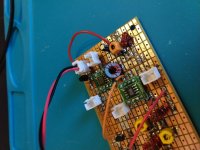
Just for fun, I decided to rework the post mixer untuned amp into a tuned amp, and see what, if any, difference this made. This turned out to be borderline difficult, since I really didn't allow room for a tuned circuit in the first instance, and I didn't want to rebuild it from scratch, which might actually have been easier.
The smallest toroids I had were T-25, and even though these are quite small compared to the T-37's, a T-25 and trimmer cap was a tight fit. I got about 1.8 microhenries worth of wire on the T-25; that and the stray capacitance floating around was enough to resonate it at 14 MHz with just a trimmer cap.
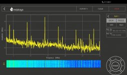
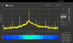
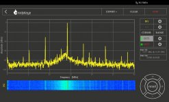
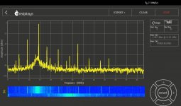
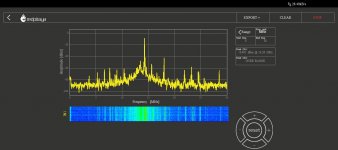
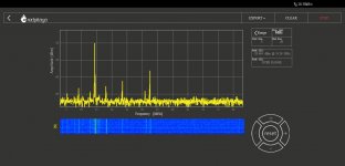
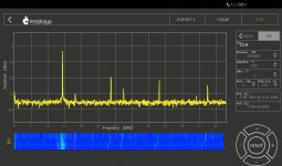
The results look to be worth the effort - the first spectral pic is the untuned amp, and the following spectral pics are the tuned amp. The improvement was substantial: about 12 dB more power at 14 MHz, and about an additional 20 dB reduction of the 9 MHz component.
The center pic was the first spectrum shot I took - I couldn't figure out what all that width was at the base of the 14 MHz output, so I flipped on the 51S-1 to listen to it, and it was AC hum. After hooking it up to a battery supply, and unplugging everything in the vicinity with a switcher, except the little wart powering the RP, most of this went away as shown in the other shots. The residual is probably the RP power supply.
I expect this won't be an issue since it is going to go in the trunk of my car. I may play some with balancing the SA602 output, or adding on a little more filtering on the DC, or I may not. I really want to be done with this board and move on.
The smallest toroids I had were T-25, and even though these are quite small compared to the T-37's, a T-25 and trimmer cap was a tight fit. I got about 1.8 microhenries worth of wire on the T-25; that and the stray capacitance floating around was enough to resonate it at 14 MHz with just a trimmer cap.
The results look to be worth the effort - the first spectral pic is the untuned amp, and the following spectral pics are the tuned amp. The improvement was substantial: about 12 dB more power at 14 MHz, and about an additional 20 dB reduction of the 9 MHz component.
The center pic was the first spectrum shot I took - I couldn't figure out what all that width was at the base of the 14 MHz output, so I flipped on the 51S-1 to listen to it, and it was AC hum. After hooking it up to a battery supply, and unplugging everything in the vicinity with a switcher, except the little wart powering the RP, most of this went away as shown in the other shots. The residual is probably the RP power supply.
I expect this won't be an issue since it is going to go in the trunk of my car. I may play some with balancing the SA602 output, or adding on a little more filtering on the DC, or I may not. I really want to be done with this board and move on.
Attachments
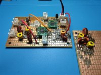
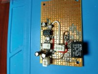
I put a ( sort of ) broadband transformer on the output of the SA602 to balance the output. The smallest ferrite toroids I have are FT-37, so it's way too big, but it's rigid, not fragile, and looks to make a substantial improvement on the suppression of both inputs, but didn't do much for that second harmonic of the 9 Mhz input.
It didn't do anything to solve that wideband noise issue. Nor did power supply filtering, isolation, etc.
I've never had anything that can "see" a wideband parasitic oscillation, but that's what I'm seeing ( and hearing - the classic AC buzz ) isn't it?
a) it shows up as soon as I put a Hi-Q tuned circuit in the drain lead;
b) it peaks at a point just slightly below the resonant frequency of the Hi-Q tuned circuit;
c) I've read that toroids are self shielding, but that trimmer is sitting right on top of one of the gates, and could be a low capacity feedback path into the gate; that extra bit of stray capacity explaining why the oscillation peak is a bit lower in frequency than the intended tuned circuit?
Is this plausible? I don't have a hot air gun here at the lake, otherwise I would just take it apart right now to test this theory.
Attachments
Last edited:
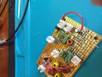
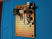
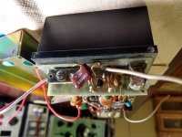
It was oscillating, so I moved the tuned circuit to the output of the SA602, where the T-25 toroid transformer was a perfect fit. There was no room for a trimmer, so I hand selected capacitors to resonate the primary of the coil.
It resonates somewhere between 56 and 82 pF. The only leaded value between those points that I had in my tool kit, was 68 pF, which is fitted. This looks pretty good, but might still have room for improvement.
I keep a penlite pack in my toolkit for power; it's down to just 8 volts, so I'm done for today, at least.
Attachments

I reworked, slightly, the tx post mixer amplifier, and, unless it just won't work in the actual radio, the low level transverter board is done. All of the IF and LO is gone, most of IF + LO is gone, but harmonics of 14 MHz are present, presumably from the BF992.
I was going to scrap out the ugly experiment board, but it occurs to me that it would not take much at all to make it into possibly the world's largest and ugliest single band 14 MHz DSB transceiver. The data sheet for the AD831 says the IF can go down to DC. I think I can put audio into the NE602 and use the balance control to null the carrier. Might not even need a speech amplifier. It has the 14 MHz bandpass filter in place and tuned up. So, for now it will remain intact, or whatever one wants to call it.
The bag of transistors are supposed to be 2N3553; about $7.00 USD for a bag of 10 from AliExpress. 2N3553 was pretty hard to find in the day, so I doubt these are genuine, however, I do have some real 2N3553 from back in the day to benchmark them, so, in due course, we shall see.
Attachments
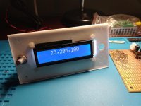
Beats having it flop around on my desk, but in no way acceptable for a car, although I suppose the longer this drags on, the more willing I am to compromise ...
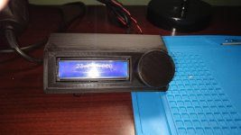
This printed in about one half hour.
edit: I think, if I can remotely master the 3d printer thing, I see no reason for the display and controls to be on the same panel - frequency display should be somewhere where it is in sight without taking eyes off the road, while volume and frequency control can be somewhere close to hand, with different shape knobs, which can be printed ...
Attachments
Last edited:
Looking good, though. 3d printing is a doddle so...
Perhaps, but I have no prior experience with CAD stuff so it is ab initio and yet another big learning curve for me. I do think once the software is useful for ordinary people, these will be as common in the home as PC's are today.
In the meantime, I've been working a bit on what I call the housekeeping board - this will have the remote volume control, a lower gain audio amp to better distribute the audio gain and hopefully improve the volume control action, T/R switching, LO splitting and conditioning, etc. It is about half done. The SG-9 handles low current voltage switching between receive and transmit, and has voltage lines to control the transverter board.
The remote volume control is an MC3340P. Obsolete, but I have a half dozen or so. The amp is an LM380N-8. On both of the chips, the bypass and decoupling caps, RC networks, etc., are under the chip to save space. It's not on the data sheets, but likely well known that in the LM386 and LM380 / 384 chip family, the bypass pin has a secondary function as a mute pin - connecting the bypass pin to ground, or to the positive voltage rail ( builder's choice ), cleanly and quickly mutes and unmutes the chip without thumps, clicks, pops, or other drama. Here, as the PTT line goes low, a '3906 type puts the bypass pin high to mute the audio chain. A similar switch toggles the TR relay.
I haven't fooled with TX subsequent to the post mixer amp pending an evaluation of the repairability ( is that even a word ?) of the 130 watt brick in the donor radio. If it is cheaply and easily repairable, the XVTR board has more than enough output to drive it directly. If it is FUBAR, then I'll have to do something else.
Attachments
For simple stuff, look at https://www.tinkercad.com/
it's free, easy and surprisingly good once you get into it...
Also always look at https://www.thingiverse.com/ - and similar sites. Often what you want has already been done, or something close to it.....
it's free, easy and surprisingly good once you get into it...
Also always look at https://www.thingiverse.com/ - and similar sites. Often what you want has already been done, or something close to it.....
I've looked at TinkerCad and some others, but apparently I'm a dolt - it just doesn't click with me.
https://apolloinrealtime.org
Now has the complete Apollo 17 mission up, and a note on the web site says they are working on 13. I think 8 would also be a good one to add.
https://apolloinrealtime.org
Now has the complete Apollo 17 mission up, and a note on the web site says they are working on 13. I think 8 would also be a good one to add.
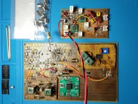
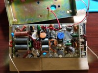
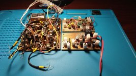
So, this is the Dentron brick, 100 watts + output at HF ( when they work ).
It is quite compact, as shown in the comparison to the proto boards I am using.
The low level input takes it's drive directly from a dual gate MOSFET TX mixer in the donor radio, so sub milliwatt to milliwatt level drive is all this requires. The TO-5 transistor is a 2N3866 so probably a watt or two out of this. This looks like it could be transplanted to my radio. I have genuine 2N3866 transistors in case this one is fried, but I would probably sub in a 2N3553 if I rob this board from the brick. I might need to bypass my TX post mixer amp.
The driver is an MRF476. I may have one or two of these in the junkbox.
The output transistors are MRF458 with a blue dot. RF parts has them, the ordinary MRF458 is $60 / piece. The "low beta" MRF458 ( which it sub lists as MRF454 ) is $26 / piece. I don't know which is applicable here. I think it likely the output transistors, or one of them, are shorted. I don't know if it is worth pursuing a repair of this, or if other transistors would work. I would like to extend the range to 6 meters, but I don't know if frequency is limited by the transistors, or the ferrite, or both. The little low level board should go to 6 easily; 2N3866 is a VHF part.
Search results for: 'mrf458'
Attachments
Last edited:
A lot of cool stuff there at Thingiverse, particularly parts to make "exotic" antennas like Lindenblad, quadrifilar helix, portable sat com dishes, and other stuff. There is a camera tripod mounted UHF quasi dish that looks ideal for Gerhard's motorcycle EME.
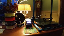
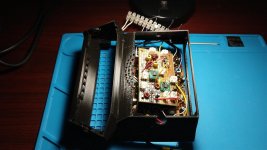
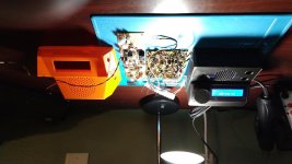
Slight progress, but this is still not something I would want to look at in my car(s). The other pic is the printer cranking out another test article ( my walls are not curved, that is "wide angle" lens on my Lenovorola).
I found a local factory: Push Plastic 3D printer filament Manufactured in USA by Push Plastic that makes PLA filament, so it is easy to just swing by the factory on a Friday afternoon, I even got a tour of the place from the owner. Still need some green, maybe sublime, or British racing green to go in the Jag. Or both.
Attachments
EME.
I think that was discussed Christmas before last, in connection with that absolutely epic monster EME array, that should be on the cover of every Ham mag in the world.
BTW, I may be the last person to have realized this, but my latest Windows update has a thing called 3D Viewer, which lets the user open some 3D objects and order them printed, at an insane cost ...
But, if you click on some of the buttons, it will take you to an online app called 3D Builder. And this app looks pretty good to me. It will easily do some things with STL files, like take objects and slice them into layers for subtraction, that I found impossible with the other newb apps.
My gut feeling is that for Newbs like me, it is a lot better than TinkerCad. Also BTW, I find FreeCad to be pretty good at converting STL files to solids, if you need to do that.
EME.
I think that was discussed Christmas before last, in connection with that absolutely epic monster EME array, that should be on the cover of every Ham mag in the world.
You can see Bernd's array on GoogleEarth
") I think that the picture still
I think that the picture stillhas the older, smaller one .
< https://www.google.de/maps/search/nordhof/@52.7178011,12.8230946,81m/data=!3m1!1e3?hl=de&authuser=0 >
I'm not really far with the transverter project for 432. I'm still moving components
on the board. I have built the input stage. Expected 0.3 dB noise factor and we
measured 3.x dB. Got the only demo board from DigiKey. Probably my SAW filter
is too narrow for the 8970B. My noise head is at Bernd's for comparison. A real
calibration would cost some €600, that's not justified.
The pic is the transverter board. it is about 2.5" * 2.5" ( 60 * 60 mm).
Top left is 432 MHz in, rx preamp, Pin attenuator, 2nd RX preamp, MCL TUF-1
ring mixer, shortwave filter, 32 MHz out SMA on right side.
The receiver part has 2 SAW filters on 432.
The big block in the middle left is an ECOC-2525 100 MHz crystal oven oscillator
with 5V CMOS out. Below is a CMOS buffer for reference output and another
buffer to drive a low pass filter to get a sine. Doubler to 200 MHz, another doubler
to 400 MHz, 400 MHz SAW filter and then 2 SOT89 gain blocks to drive the
LO_in of the the 2 Ring mixers.
Bottom row is from right to left: SMA 32 MHz in, short wave filter, TUF-1 ring mixer,
432 MHz SAW filter, pre-driver and output driver to 1.5W , then SMA out.
All that runs on 5V like the Red Pitaya. The PA is a NXP MRF6V2150 50V
power FET, it can do 23 dB gain and 150W out. Or whatever a dozen of
18650 Li Cells will allow. PA is a different board and box.
I'll modify the Red Pitaya to run from the 100 MHz crystal oven instead of its
own clock.
Sigh, all of that is advancing quite slowly.
73 & cheers, Gerhard DK4XP
Attachments
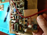
I worked some on mine this afternoon.
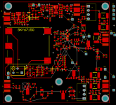
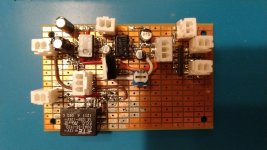
Added the signal conditioning for the LO. It's laid out poorly, and may need to be redone. It's calibrated for the DDS, the Si5351 will need addtional attenuation off the board. The DDS and Si5351 require different voltages; I added an adjustable regulator to accomodate either, and any voltage drop on the way to the control head. I didn't have any coax, so I have not finsished two connections to the TR relay.
The housekeeping board is denser than I anticipated, but I still have empty space for one or two TX power stages if needed. I'm a little surprised at how many connectors it takes to cable everything together. At least the connectors are cheap.
Attachments
...all of that is advancing quite slowly. ...
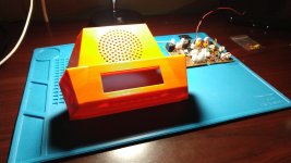
I think I am at the point where I can think of cabling this all together and packaging it ( even though I am still only at mw TX levels ), and being able to print some boxes has made me ( maybe ) rethink how I want to do this.
I had planned on using the printed box just as a less ugly way to hold the tunable local oscillator/frequency display and the knobs, speaker, etc. Everything else would be in the fugly metal box back in the trunk.
But the SG-9 IF board is pretty small. It fits easily in either of these boxes. I half printed that funky box so I could see down inside it, and there looks to be room for the transverter board above the SG-9; likewise with the square box. With everything in one box, the housekeeping board would be mostly eliminated - I would not need the remote controlled attenuator for the volume control, and could use the audio amp built into the SG-9. All I would need would be a TR relay, and the regulator for the local oscillator power supply. I could use that metal box for the transmit PA.
So now I'm not sure which way I want to proceed. I guess that's a good problem.
Attachments
Last edited:
In Georgia the ham club meetings are cancelled (just like everywhere I presume) and to replace them and keep everyone in contact there are nightly nets on 80 meters. Makes me want even more to get a radio on HF, but I don't have anything working at the moment, and my RF design chops aren't quite up to it.
But keep up the posts, I'm still following along.
But keep up the posts, I'm still following along.
In Georgia the ham club meetings are cancelled (just like everywhere I presume) and to replace them and keep everyone in contact there are nightly nets on 80 meters. Makes me want even more to get a radio on HF, but I don't have anything working at the moment, and my RF design chops aren't quite up to it.
But keep up the posts, I'm still following along.
You can buy a Swan 350 or a Drake TR4 for $100 - $125. No necessity of re-inventing the wheel. These are still top-flight rigs!
- Home
- Member Areas
- The Lounge
- No RF gear here?