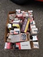
...Any numbers / symbols at all on the parts?
The dimples on the parts make the numbering / trade dress illegible.
I sent the seller a message asking for the part numbers.
If I get any type of an intelligible reply, I'll post it.
... Even more radical: "stuff" some RF in and see what happens.
I'm not sure I have the correct adapters to get from SMA to the SO-239 or N on my dummy loads and watt meters, so putting RF into it may be a week or two off.
Win W5JAG
Seller says he'll get me the part #'s after Chinese New Year. Uh, ok ....
They are both MMIC's on close inspection. First chip looks to have M3043N or M3943N as part number, Runs off a bit less than 12 volts. No apparent manufacturer marks.
PA has K6 on it. Runs off 12 volts. There is a "P" inside the dimple in the middle of the chip.
Win W5JAG
They are both MMIC's on close inspection. First chip looks to have M3043N or M3943N as part number, Runs off a bit less than 12 volts. No apparent manufacturer marks.
PA has K6 on it. Runs off 12 volts. There is a "P" inside the dimple in the middle of the chip.
Win W5JAG
The data sheets that I have from my days as an RF engineer are all obsolete. All the smaller players in the RF chip business either died off, or were gobbled up in the industry consolidation that started about the time I left the game. There were several companies that made chips that needed only a resistor from a DC supply for bias. Sirenza and RFMD come to mind, but both have been eaten by the big fish like Quorvo and Broadcomm. There are still a few dozen parts that fit the circuit in the Digikey and Mouser RF list, although the list gets shorter when you look for response down to 1 MHz. Look at the test circuit in these data sheets:
The second chip is a mystery. The board states "2 watts." That would be the maximum saturated power at a given low frequency like 50MHz. It also states 32 dbm P1db. 32 dbm (1.6 watts) as the P1db point. This is the power level where enough gain compression sets in that 1 db of gain has been lost, as well as considerable linearity. This is where you want to set the overall gain such that you hit this point on maximum modulation peaks for SSB use.
For a chip to be roughly 50 ohms over a large bandwidth, the output impedance of the device itself needs to be close to 50 ohms at max power so that the matching needed is minimal to minimize losses. You can get 2 watts with 5 volts on the drain of any modern process technology, yet this part is clearly connected directly to the 12 volt supply through a choke.
All the 12 volt parts listed in Digikey are tagged "obsolete." I have no clue what it really is.
Attachments
I verified that the bias resistor on the input stage is in fact 82 ohms.
The product marking seems to rule out the Mini Circuits part and the Sirenza part.
The expected voltage drop across the 82 ohm resistor, and the simple circuit, looks spot on for the RFMD part. That seems to be the most likely candidate of these three, and if that is not the actual part, it sure looks like a good replacement.
The "K6" marking on the output chip is transverse, rather than longitudinal, but my first thought was that it was a Mini Circuits part because it looks like one of their cryptic part numbers ...
I skimmed Mouser, but didn't see anything that could run straight from 12 volts as that last chip does.
Thank you for looking up those sheets. I guess we will have to see if the seller can supply actual part numbers.
Win W5JAG
RFMD part.
RFMD no longer exists. It was swallowed up along with Triquint and Sawtek when Quorvo came into existence. I have no idea how many of their older parts are still being made.
< HF-Verstarker | RF/IF und RFID | DigiKey >
There are lots of such amplifiers. 7 pages. I have limited the search to sot89 and "active".
12V operation of such a thing does not make sense. Remember that
the momentary collector/drain/whatever voltage would go to 24 Volts and
that does not go together well with 1W into 50 Ohms.
There are lots of such amplifiers. 7 pages. I have limited the search to sot89 and "active".
12V operation of such a thing does not make sense. Remember that
the momentary collector/drain/whatever voltage would go to 24 Volts and
that does not go together well with 1W into 50 Ohms.
Last edited:
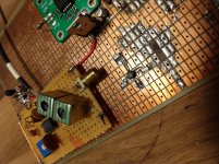
I hooked up the broadband amp, and got nowhere with it.
The power LED lights up, and it draws 250 ma static current, but that's about it.
I could not get it to produce any RF at the output. The output goes from the amp into a Drake W7 wattmeter, and from there into a Drake DL-300 dummy load. I tried driving it from the output of the mixer and could not get any detectable RF out of it. Thinking I just didn't have enough drive, I hooked the FeelTech to it, and started at 0.1 V and went up to couple of volts. Nothing. Finally, I hooked a 2 meter HT up to it, and hit it with about 500 mw at 146 and 440 MHz. Nothing. Zip. Nada.
I tested continuity through my cables, and they were good. The input network doesn't look at all right to me, but I'm a ham, not an engineer, so I left it alone for now. Interestingly, putting RF on the input causes a significant reduction in standing current, down to about 100 ma. That doesn't seem right.
So, typically, something that was supposed to be a drama saver, looks like more drama. Any suggestions for replacement chips? It looks like the board uses a pretty standard layout.
If I make my own driver, should I make it broadband or narrowband? I have 2N3553, 2N3866, 2N5109, and maybe some TO-39 VHF MRF series transistors in stock.
Moving on to another failure, I have been trying to use zener diodes to lift the ground terminal of a 78LXX regulator a few volts above ground to increase the voltage output. This seems to work fine with ordinary diode junctions, but not with zeners; the output regulation is very poor - it drifts around up to one half volt, and the zener voltage doesn't translate to an output voltage as expected. I tried loading it a bit with an LED, and, if anything, this made regulation worse. It certainly did not improve it. The three terminal is bypassed with 10uF at the input, and .01 at the output, so I don't think it is oscillating.
I can't tell if this is:
a) a bad idea that just won't work; or
b) bad zeners
Am I wasting my time with the zener idea? Should I just go with a voltage reference network between output and ground, like on the LM317 series, to boost the output?
Win W5JAG
The 78xx series regulators like many vacuum tubes have gone through several design changes over their 40+ year life, and like the tubes the data sheets were not always updated to reflect the changes.
These parts started their life on an analog bipolar semiconductor process with a minimum geometry in the several micron range. These semiconductor fab lines no longer exist, so the parts go through a constant evolution to stay compatible with modern high volume processes.
The original 7805 sucked several milliamps through it's ground leg, so sticking one or more diodes, LED's or even zeners in the ground leg was an acceptable way of adjusting the output. I have even been known to stack 7805's with the ground leg of one tied to another's output. This only works if the bottom chip is loaded, but this was the days of static RAM, TTL, and HC chips on DIY computer boards and things were usually running near meltdown, so load current is not an issue.
Today the proper way to handle this is to swap the 78XX for am LM317 and two resistors. Trying the two resistor trick on a 78XX may or may not work since the 78XX doesn't specify a constant ground pin current.
I have found that all 78XX chips are NOT created equal either. The dropout voltage spec is still 2 volts in the data sheet, but I have some chips that work below 1 volt and some that need almost 2 volts. Both are Motorola parts, and Mot hasn't made linear chips in over 25 years. I imagine that things have only gotten worse, and many of the "78XX chips" seen today are probably one of the newer fixed voltage designs.
Lacking the desire to do this, you can usually fudge the current through the zener in the same manner that the LED in the cathode people get the LED into the flat part of it's curve, with a resistor to B+.
Add a resistor from the ground pin / zener connection to the voltage source / input pin of 78XX. Set the value to force a few mA through the zener even if there is no 78XX chip present.
Thanks, guys.
I have almost a hundred of 78L05 and 78L12, and three or four TL317, so at some point I will have to try the two resistor trick to make full use of my existing stock.
I thought about trying this; I wasn't sure what, if any, consequence there would be to the 78L05 by putting a positive voltage at that circuit point.
Actually, all I need is a couple of volts - even though the SA612 mixer board seems to work fine at 5 volts, I wanted to bump a 78L05 to about 7 volts or so, just because more voltage seems better than less voltage ... I suppose, if I need to bias it, instead of using a zener, I could just use an LED to get the couple of volts.
Win W5JAG
... Trying the two resistor trick on a 78XX may or may not work since the 78XX doesn't specify a constant ground pin current.
I have almost a hundred of 78L05 and 78L12, and three or four TL317, so at some point I will have to try the two resistor trick to make full use of my existing stock.
... Lacking the desire to do this, you can usually fudge the current through the zener in the same manner that the LED in the cathode people get the LED into the flat part of it's curve, with a resistor to B+.
I thought about trying this; I wasn't sure what, if any, consequence there would be to the 78L05 by putting a positive voltage at that circuit point.
Actually, all I need is a couple of volts - even though the SA612 mixer board seems to work fine at 5 volts, I wanted to bump a 78L05 to about 7 volts or so, just because more voltage seems better than less voltage ... I suppose, if I need to bias it, instead of using a zener, I could just use an LED to get the couple of volts.
Win W5JAG
Adding a few ma to the zener worked, and brought the output up by the zener voltage.
I then removed the zener, and installed a floor sweeping quality, yellow LED, in its place. Interestingly, the LED lit, and brought the output to 6.9 volts without any need for additional positive voltage. Adding a few ma to the LED brought it to 7.2 volts output, but, considering the trouble of adding in a 1206 resistor after the fact, probably was not worth the effort. I was afraid an 0805 might overheat.
I did not get a chance to try the two resistor trick.
Win W5JAG
Attachments
It appears that all three tricks can still work, if, like me, one is over stocked on 78XX.
I pulled the LED, and used a 680 ohm resistor for the sense resistor, and a 1.2K resistor in the ground leg, and got 7.7 volts out of the 78L05.
Input is from a 7809 that powers the AD831 board, so overhead is probably marginal, but it only needs to supply 3 ma. It is not convenient to pull the voltage for the 78L05 from a higher potential.
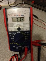
Yes, it's really a DMM with a high input impedance (10M IIRC). The analog meter reading is derived somehow, and seems fully protected from slamming the peg on overloads or reverse polarity. Still very useful for looking at changing voltages, currents, etc.
The variety of inexpensive, hobby grade, test stuff on eBay is breathtaking. AliExpress probably more so, but eBay always seemed more convenient to me.
Win W5JAG
I pulled the LED, and used a 680 ohm resistor for the sense resistor, and a 1.2K resistor in the ground leg, and got 7.7 volts out of the 78L05.
Input is from a 7809 that powers the AD831 board, so overhead is probably marginal, but it only needs to supply 3 ma. It is not convenient to pull the voltage for the 78L05 from a higher potential.
Clever VOM.
Yes, it's really a DMM with a high input impedance (10M IIRC). The analog meter reading is derived somehow, and seems fully protected from slamming the peg on overloads or reverse polarity. Still very useful for looking at changing voltages, currents, etc.
The variety of inexpensive, hobby grade, test stuff on eBay is breathtaking. AliExpress probably more so, but eBay always seemed more convenient to me.
Win W5JAG
Attachments
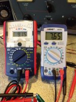
Well, the listing says 10M; if there's an easy ( not time consuming ) way to check it, I can try to determine exactly what it is. It has no provision for zeroing the meter like a traditional VOM:
KT7310 portable digital analog dual display multimeter 9 functions in 24 ranges | eBay
Of the cheesy, cheap, ebay DMM's out there right now, this one is actually my favorite - it has a graphical display with a bandwidth out to about 15-16 KHz. It's pretty good at measuring very small AC voltages. Of course, in true fast and loose fashion, it's typically listed as an oscilloscope.
I parted out something with a small number of Burroughs nixie's in it; can't remember their part number off the top of my head - I'm sure I'll never use them. I have a fair idea of where they are. PM me an address if you want / need them to keep something going ...
Win W5JAG
Attachments
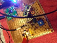
No real progress to speak of - since the tx mixer output looks clean, I dropped one of the NEC upc1651 MMIC's ( last seen as an unsatisfactory broadband amp on the alternate, perf board based, wideband front end ) on to the current board to play with as a gain block. Haven't tested it yet, other than to verify it draws the correct amount of current. Should work, may need some matching at the input.
Since I haven't had much time to work on this, I bought an extra SMD rework station and I've been putting together a travel kit of extra tools / very modest test equipment / common use leaded and SMD parts to allow for a little bit of work when I am at the lake house, or even in spare time at the office.
This was the first test of the travel package - done last weekend on the kitchen table at the lake house after everyone was asleep ...
Win W5JAG
Attachments
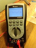
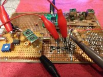
I tried driving the upc1651 direct from the secondary of the last transformer in the bandpass filter, and the results were unsatisfactory. I was not able to get much RF out of the upc1651, It was unable to drive the 50 ohm load.
I added a small LC network to match the bandpass filter output ( I guessed this was about 1000 ohms ) to the 50 ohm input of the upc1651 MMIC, and added a second upc1651 in the signal path, thinking that the matching would be poor, and that two chips would be needed to get to the rated +5dbm output of the upc1651 chips.
The second chip smoked out as I was bringing up the voltage. I took a look with the scope ( second pic ) at the input to the second chip, and apparently I got the matching pretty close to right - it sure looks like a peak of +5dbm at 50 ohms going into the second chip. The waveform out of the first MMIC looks pretty good.
So, I'm going to have to pull that second chip and select a more robust 50 ohm gain block, or maybe go with a narrow band gain stage. I'll have to think on it some. I would like to get to about 200 mw or so, which I think will be enough to drive an external power amplifier.
Win W5JAG
Attachments
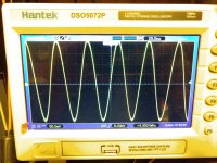
So, assuming I am at +5 dbm peak at 50 ohms, as it appears I am, I need another 15 to 18 db if my arithmetic is correct.
Tubelab suggested this chip as a gain block several months ago:
Mouser Electronics
I took another look at the datasheet, and it looks like it could take me to 20 dbm ( 100 mw ) but the spec sheet cuts off at 50 MHz on the low end.
Has anyone tried this chip at HF? They have a suggested layout, that I am not presently equipped to duplicate - how critical is layout for these gain block type parts at HF / low VHF?
I just received an order from Mouser last Friday; wish I had foreseen the need to get some gain blocks. I think I would prefer to learn how to use modern, single chip, broadband 50 ohm parts, rather than build up a strip from discrete parts, even though I have the parts for the latter, maybe even some built up and tested blocks that just need a tuned circuit or maybe a broadband transformer to finish them, on hand.
edit: one other question - is 15 to 18 dB feasible for one stage? Or do I need two?
Win W5JAG
Last edited:
- Home
- Member Areas
- The Lounge
- No RF gear here?