Member
Joined 2009
Paid Member
Hi
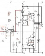
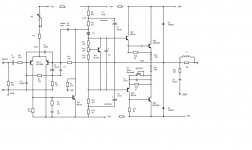
My new schematic.
What is yours opinions?
It looks very nice to me. The no-miller compensation is what I used in my recent TGM6 amplifier (there's a thread on this forum for it).
I like the double bootstrap a lot. I may use this on a new design of my own sometime. I think it's a very good topology for use with MOSFET outputs since it allows a higher swing and therefore more efficient use of the power rails. I suspect it may also help reduce turn-on and turn-off noises.
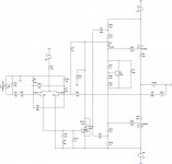
Could someone run a simulation my amplifier? Can anyone Help?
Thanks
Guillermo
It is my pleasure to run a simulation for you
")
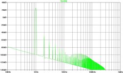
The distortion profile looks VERY GOOD into a linear load.
I'm so impressed I may have to start a new project on a variation of this design
Attachments
Last edited:
Hi Gareth.
Thank you very much for simulate my circuit. Been a long time and have been following other thread (Naim, a simple quasi-complementary 50W amp - Gaetan8888).
I have to propose some changes: reducing R18 to 33R give a better thd spectrum. Also try using a 10 nF across the baxandall diode.
Thanks
Guillermo
Attachments
Member
Joined 2009
Paid Member
I don't think the double bootstrap is the main reason why the FFT looks like it does, but of course every element of the circuit will affect the sound. You could run the simulation without the double bootstrap (i.e. single) and see what you get ?
Many people say bootstraps sound nicer than constance current sources (CCS) for the VAS. What I like about the profile is the decreasing scale of harmonics - the 'Hiraga' profile as I like to call it. I believe it tends to sound less-clinical but still clean.
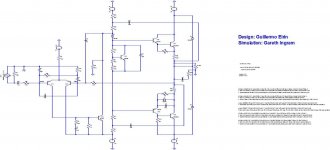
What I like about the double bootstrap is the ease of using MOSFET outputs. Normally you need much higher voltage rails due to the higher turn-on voltage of vertical MOSFETs but in your double bootstrap approach the VAS can swing well beyond the rails and allow a much more efficient design. MOSFETs aren't something I know much about, but people say they are more rugged, have no beta-droop at high current and don't require as low an impedance driver stage. They do have a gate capacitance that needs to be charged and discharged at high frequencies. The double bootstrap works well for this but upgrading the VAS to a complimentary feedback pair is a way of providing stronger drive to the output stage and it shields the input pair from the Class AB swings of the output. I've attached a schematic that also simulates nicely.
The other trick that you should really try to do is reduce the turn-on thump that is usually associated with a single bootstrap. Your double bootstrap should be better - although the capacitor in the feedback circuit is another item that needs care to avoid turn-on noises.
I think the quasi-comp output stage helps a lot with the distortion profile. But if you changed from an LTP input to a singleton input you could achieve similar benefits.
Many people say bootstraps sound nicer than constance current sources (CCS) for the VAS. What I like about the profile is the decreasing scale of harmonics - the 'Hiraga' profile as I like to call it. I believe it tends to sound less-clinical but still clean.
What I like about the double bootstrap is the ease of using MOSFET outputs. Normally you need much higher voltage rails due to the higher turn-on voltage of vertical MOSFETs but in your double bootstrap approach the VAS can swing well beyond the rails and allow a much more efficient design. MOSFETs aren't something I know much about, but people say they are more rugged, have no beta-droop at high current and don't require as low an impedance driver stage. They do have a gate capacitance that needs to be charged and discharged at high frequencies. The double bootstrap works well for this but upgrading the VAS to a complimentary feedback pair is a way of providing stronger drive to the output stage and it shields the input pair from the Class AB swings of the output. I've attached a schematic that also simulates nicely.
The other trick that you should really try to do is reduce the turn-on thump that is usually associated with a single bootstrap. Your double bootstrap should be better - although the capacitor in the feedback circuit is another item that needs care to avoid turn-on noises.
I think the quasi-comp output stage helps a lot with the distortion profile. But if you changed from an LTP input to a singleton input you could achieve similar benefits.
Attachments
Last edited:
Member
Joined 2009
Paid Member
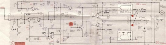
I have no experience with GP 140/145 as shown on the Grundig schematic but Darlingtons generally use lower bias settings because the drivers are forced to follow the output transistors as their temp. fluctuates wildly. As all BJT errors seem to end in smoke, you can guess that means a bias that swings drunkenly also..... - although their choice of bias looks on the low side, they are asking for only 15mV across each emitter resistor at the output where I would be looking for 26mV.
EF driver transistors have near constant dissipation, hence their thermal stability could be considered a better operating condition. Perhaps this is why even Sanken's SAP15 and 16 pairs, with internal thermal sensing diodes, were still problematic with thermal runaway.
Member
Joined 2009
Paid Member
I've not heard this explanation before - it doesn't make sense to me - maybe I'm being dumb though. As you say, the die temperature is determined by the power device and it's temperature is stabilized by the emitter resistors. The use of 26mV across the emitter resistor is to minimize distortion, I don't see it being a big factor in the thermal stability.
Perhaps I don't explain very well....
Some kit construction and design notes I have seen on integrated Darlington audio amplifiers have also recommended low bias levels because the thermal influence of the output transistor on the driver which, apparently, is significant. I have tried to observe this on the 'scope in 'subtract' mode using LF sinewaves, comparing Vre with Vbias as power is increased. The difference between discrete and integrated output stages (BDV64/65, TIP142/147, MJ100XX etc) is quite noticeable as power climbs above 10W or so. This suggests to me that with a standard Vbe multiplier control and bias setting, the bias could still run away or at least increase well beyond set levels as power increases toward max. limits.
The easiest way to ensure this doesn't happen is probably as here, by limiting the bias to a level that remains controlled in all forseeable situations. Otherwise, you're up for a more sophisticated control system. There is still the possibility that the designer wasn't concerned about lowest THD, as you may infer, and just elected to use an easily trimmed value that was cheaper, yet gave acceptable results. I have to remind myself that these BJT devices are really outmoded industrial switcher parts which don't rate with class AB hi-fi, as I see it, anyway.
I think the reason few have stability problems with Darlingtons is the same as with a lot of audio amplifier DIY and even commercial audio products - we use them at low average levels and a lot of sins go unnoticed - until we throw a party, that is.
Member
Joined 2009
Paid Member
I can understand that with the two junctions in series, in the Darlington, that if they are both on the same heatsink the Vbe multiplier has to be well positioned so that it has adequate control over the output. By mounting the Vbe multiplier onto the active device and not onto the larger thermal mass of the heatsink the thermal control loop can be made much more effective. Still, it's good to know that practical experience with them has been that they can be troublesome. My own experience is limited to Sanken Darlingtons - see my thread on TGM6 - which was thermally stable when optimally biassed for Class AB although I never ran it hard to see how stable it was at high heatsink temperatures.
Ian - what's your take on the benefits of the double bootstrap ?
Ian - what's your take on the benefits of the double bootstrap ?
Last edited:
I only wish I knew my own mind on it. I'm tempted to see it as you described - a good approach to full rail swing of the VAS. That must be good for efficiency and economy and we've seen from your sim. that it doesn't hurt a fabulous harmonic profile either. I would think AKSA has had a look at this more than once and probably could give a more useful reply - It's his kind of territory, if he's out and browsing following his new NAKSA creation..... what's your take on the benefits of the double bootstrap ?
It really is necessary to see a standard single boostrap sim. in Geirin's design. Otherwise, without pottering about with the sim. it's hard for me to assess the potential, since THD is already running high at ~ -60 dB. There may be ways to improve this, since single bootstrap designs, as we've seen here in several popular threads and texts, need only increase THD from say, .002% to .004% in a careful implementation. (That figure refers to a design with the basic topology of Self's blameless model amplifier or the RCA design it derives from).
I can't imagine double bootsrapping would suddenly render it diabolical but it will affect the linearity, having higher impedance terminations at both rail reference ends of the VAS output. Perhaps this is why we don't see it too often.
OTOH, it may now be making just the kind of distortion contribution we were all looking for.
Member
Joined 2009
Paid Member
Indeed, the 2BS is very old, and I concur with Bigun's comments about driving the mosfets above and beyond the rails. This is a huge advantage as it brings rail efficiency of mosfets up to the same high level of bipolars, but much easier to drive.
The distortion profile is a great advantage with a singleton, as Gareth says. Other techniques are needed however to ensure a monotonic decrease of the harmonics, often at the cost of increasing distortion of the even harmonics. Note that on the TMOS amp uses asymmetric 2BS topology.
Am I the only one who believes in monotonic decrease of the harmonic distortion?
Hugh
Am I the only one who believes in monotonic decrease of the harmonic distortion?
Hugh
No. I follow your design philosophies when I made kit version of Perkutut Amplifier (refining from my blog version). It have many fans here.
Thank you, Mr. Hugh.
Btw, I still preferred very low THD in all audio frequency and high slew rate.
Btw, I still preferred very low THD in all audio frequency and high slew rate.
Hi Bimo,
Greetings!
Since you are technically minded, and you love the intellectual pursuit, you naturally will prefer this approach because it seems better to match the output with the input, BUT, a lot of people do like the monotonic harmonic reduction - like the tube amps, which mostly do not use much global feedback.
It's like food; some like sweet, some like savoury.........
Hugh
- Status
- This old topic is closed. If you want to reopen this topic, contact a moderator using the "Report Post" button.
- Home
- Amplifiers
- Solid State
- No Miller cap, Double bootstrapping amp.