Hi thanh
Why don't you download a free copy
of MicroCap 7 ( student version)
at
http://www.spectrum-soft.com/download.shtm
it is very powerful and friendly
regards
Federico
Why don't you download a free copy
of MicroCap 7 ( student version)
at
http://www.spectrum-soft.com/download.shtm
it is very powerful and friendly
regards
Federico
Re: Here's the topology of this setup.
Where did you get this topo ? Your idea ?
For me it seems to work good, it could also be a noninverting version.
Just it comes to my mind now, if the error amp - in this case both - carries large signal swing @ the same time, will the error signal be as clean as if it was a pure error amp that carries small signal swing only ?
My problem is that in the end I need a version with single ended output because it is not possible to drive the tube of my plasma tweeters balanced.
Or I stay with transformer.
unitgain said:The amp is a bridged pair of "audioamps" from the LTSpice examples directory. Substitute your favourite model here.
Where did you get this topo ? Your idea ?
For me it seems to work good, it could also be a noninverting version.
Just it comes to my mind now, if the error amp - in this case both - carries large signal swing @ the same time, will the error signal be as clean as if it was a pure error amp that carries small signal swing only ?
My problem is that in the end I need a version with single ended output because it is not possible to drive the tube of my plasma tweeters balanced.
Or I stay with transformer.

Re: Here's the topology of this setup.
I looked through the thread and realized that I never posted my enhanced circuit which might be similar to this one. I forgot. And never fiddled values to see how low thd can go in the sim No time for that yet.
unitgain said:The amp is a bridged pair of "audioamps" from the LTSpice examples directory. Substitute your favourite model here.
I looked through the thread and realized that I never posted my enhanced circuit which might be similar to this one. I forgot. And never fiddled values to see how low thd can go in the sim No time for that yet.
Re: Re: Here's the topology of this setup.
Yes, though people have pointed to similar topologies elsewhere. There's probably a relation to the X topo as well, but I'm not sure exactly what it is. Remember, I'm new to this stuff!Bernhard said:Where did you get this topo ? Your idea ?
Can't find my attempts to have signal swing on both sides...
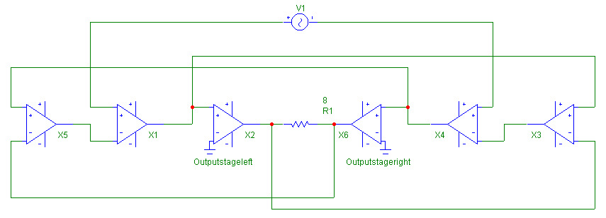
Here my extended version K2 -175 K3 -160 without fiddling.
Fiddling would take a day because the sim is slow on this schematic.
The reasons why I did not post it are obvious
Try to understand that... If you look on the left side only, it's easy.
The main input is subtracted from the left output = error of left side, and this error is again subtracted from the main input.
Same on the right side plus error of the left side is reamplified to cancel across the load.
[img]http://www.beautyphoto.de/extended.jpg
I have not got PC.I enter here at internet coffee.Hi thanh
Why don't you download a free copy
of MicroCap 7 ( student version)
at
http://www.spectrum-soft.com/download.shtm
it is very powerful and friendly
regards
Federico
Thanks!
Here is unitygain's version changed to non-inverting:
All op amp symbols means differential amp: +input - -input = output.
In the sim with real circuit I get best values ever for non fiddled resistor values.
Gain = 1 but same output voltage like in other circuits:
Vop = 4V referred to ground on each side.
K2 = -220dB
K3 = -175dB
All op amp symbols means differential amp: +input - -input = output.
In the sim with real circuit I get best values ever for non fiddled resistor values.
Gain = 1 but same output voltage like in other circuits:
Vop = 4V referred to ground on each side.
K2 = -220dB
K3 = -175dB
new topo
Here is a new circuit, simplified as in above posting:
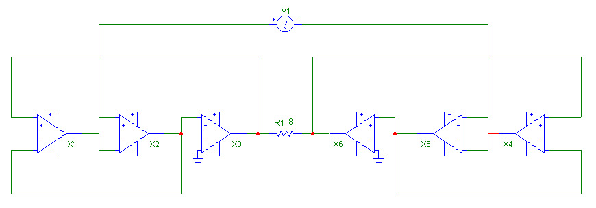
What is very interesting is that the distortion numbers are absolutely identical with the topo of above posting.
K2 = -232 dB Sorry, typo error in above posting...
K3 = -175 dB
higher orders also -175 dB.
Still had no time for fiddling values.
I believe it is worth to do all permutations of possibilities and that will sooner or later result in zero distortion.
Already with 1 Vop K2 = -247 dB = same as sine source.
Here is a new circuit, simplified as in above posting:
What is very interesting is that the distortion numbers are absolutely identical with the topo of above posting.
K2 = -232 dB Sorry, typo error in above posting...
K3 = -175 dB
higher orders also -175 dB.
Still had no time for fiddling values.
I believe it is worth to do all permutations of possibilities and that will sooner or later result in zero distortion.
Already with 1 Vop K2 = -247 dB = same as sine source.
Re: Now this is strange.
Bernhard, this is simulation. In real life the sides do not match perfectly. In this situation I think cross-coupled topo will win. Try to introduce a little asymmetry to the sim and see.
If you have some chip amps you can try to conduct a quick experiment with them. I'm waiting for my samples...
Bernhard said:The new circuit does not have a connection to the other side, except for the source and the load.
Both sides output stages have K2 and higher of -128dB
But across the load it is -232dB.
Bernhard, this is simulation. In real life the sides do not match perfectly. In this situation I think cross-coupled topo will win. Try to introduce a little asymmetry to the sim and see.
If you have some chip amps you can try to conduct a quick experiment with them. I'm waiting for my samples...
Re: Now this is strange.
yes, the symmetrical harmonics cancels out on the output (with a "bridged" amp)
but I don't understant why the 4th, 6th, 8th... aren't also -232dB down
Bernhard said:The new circuit does not have a connection to the other side, except for the source and the load.
Both sides output stages have K2 and higher of -128dB
But across the load it is -232dB.
yes, the symmetrical harmonics cancels out on the output (with a "bridged" amp)
but I don't understant why the 4th, 6th, 8th... aren't also -232dB down
Re: Re: Now this is strange.
Only K2 is -232, K3 and higher orders are -175.
I will make a summary of all simulated topos soon.
Bernhard
Bricolo said:
yes, the symmetrical harmonics cancels out on the output (with a "bridged" amp)
but I don't understant why the 4th, 6th, 8th... aren't also -232dB down
Only K2 is -232, K3 and higher orders are -175.
I will make a summary of all simulated topos soon.
Bernhard
I tried to combine the new "crossed" and "same side" topos.
First made the same side to correct the amps on each side and then on its inputs subtracted the inverted error signal from the other side like in the crossed topo.
The sim gives error message "matrix is singular"
First made the same side to correct the amps on each side and then on its inputs subtracted the inverted error signal from the other side like in the crossed topo.
The sim gives error message "matrix is singular"
Hi,
IMHO I must say that I don't really understand the point using some kind of error correcting circuit or other kind of topology that should "cancel" the distorsion.
Imagine every amplifier stage have it's own delay from input to output, using several amp stages in some kind of error correcting circuitry just add up to the delay chain and distorsion sum.
Another thing, there is an asymmetric distortion profile for every amplifier/-stage, if we use an equal inverting amp stage etc in order to correct the non-inverting amp stage, it has an distortion profile that will never match because of the assymmetric distortion difference between positive half and negative half of the signal and thereby even further add up to the distortion sum.
So the sum is that we will final up with a complex chain with a complex distortion pattern, even if it's low.
A single and accurate stage is what I would go for.
Chaining give in the end strange loop phenomenom and even possibilities of echoing, maybe not in the audible range but anyhow.
And we should not forget also that the output can also reflect back into the driver stage etc. eg. even further problem.
I think this is an academic question in the theorethic world that will never be solved in the realistic world until we are able to at least make a perfect complementary pair of semiconductors or semiconductors that have a symmetric distortion for the full sleewing signal that is handled.
Sorry if I'm standing on somebodys foot but I must admit that I have never understood at least from a realistic point of view of this thread, appoligies me!
But theoretically it's a worthwhile topic, and everything should be discussed.
Perhaps maybe somebody will come up with something after this post that give new views in the matter, and even I might consider this again.
Cheers!
I think that we are trying to simulate the symmetrical topo,balanced input and balanced outputif we use an equal inverting amp stage etc in order to correct the non-inverting amp stage
speed of holes is lower than speed of electron.So spice model of NPN is not similar to spice model of PNP.speed of holes is less than speed of electron.So spice model of NPN is not similar to spice model of PNP.
Bernhard,distortion of OPA2134 is lower than NE5532
- Status
- This old topic is closed. If you want to reopen this topic, contact a moderator using the "Report Post" button.
- Home
- Amplifiers
- Solid State
- no mercy distortion killer circuit