Hi,
Does the "tweet" always appear, with or without the input grounded ?. What are the most sensible wires to move ? input ones ? supply ones ?
Tried adding a small ceramic cap (100pF-470pF) between input and ground ? (Add it close to the input diff pair, before signal enters the gate stopper, and not close the input jack)...
Have a scope ? Is the noise still here with no output load ?
JEKYLL,
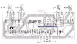
If it is a "layout problem" here is a simple test to perform:
The copper going to the gates follows the Output on a very long path, on the right part of the circuit.
so could you cut the copper under the two red crosses ;
Make 2 thin cuts with a cutter, width 0.5 mm and remove the little strip.
then drill two 0.8/1 mm holes just beside the copper and use a wire in Blue to connect the 2 parts as drawn, use a small 0.7 mm insulated copper wire.
Note: drill the holes just near the copper, if this is not the problem you can quickly go back in time, first remove the wire then solder across the 2 cuts...
PS: See the attached schema.
Regards.
Alain.
Attachments
One more thing to try ...
JEKYLL,
also, it might be worth trying to move the gate stopper resistors even closer to the output devices - for example use a resistor as the lead between the PCB and the transistors.
The value of the stopper is not so critical so you could just add another (say 50% of the original) in series to save you the effort of de-soldering or shorting the one already on the PCB (and quicker to undo if it doesn't work) .
dave
JEKYLL,
also, it might be worth trying to move the gate stopper resistors even closer to the output devices - for example use a resistor as the lead between the PCB and the transistors.
The value of the stopper is not so critical so you could just add another (say 50% of the original) in series to save you the effort of de-soldering or shorting the one already on the PCB (and quicker to undo if it doesn't
work) .dave
Just for clarification, the ceramic cap was just intended to check if the tweet was coming from a parasitic antenna behaviour of input wires. Never mentionned to leave it on all the time ")
BTW, looking at Aleph L, P, and Ono schematics, noticed the 680pF cap at all the outputs ? Wonder what is it for ?
And same question as before : Is the tweet load-dependent ?
BTW, looking at Aleph L, P, and Ono schematics, noticed the 680pF cap at all the outputs ? Wonder what is it for ?
And same question as before : Is the tweet load-dependent ?

If yes with both channels, and I remember that all measured voltages are ok, and you have tried the proposed variations with your PCB, then I believe the problem is coming from outside PCB. Nothing wrong with the installed components. Nothing wrong with the soldering.
Could we know how the wires are arranged between PCB connection points and the other ends?
Could we know how the wires are arranged between PCB connection points and the other ends?
Rectifier
Jekyll,
A friend told me one's that, if a rectifier bridge is damaged or broken, you have a 100 HZ signal in your power supply. Don't undersand it totaly, but maybe this is the case whith your amp.
I've build myself a Alpeh 30 and it humms also.
Next thing I will check is the 2 rectifier (made of MBR1090) rated at 10 Amp @ 90 V. Ik hums not loud but noticeable at 30 cm from speakers. Maybe the rectifier diodes are rated to low, and I should use the MBR2045. ( 20 A @ 45 V) or even the MBR3045.
please some feedback for the rectifier thing.
Nils
Jekyll,
could it be that you used the wrong value component somewhere in the circuit? Most likely a cap 10 times too small / too big. Or a resistor of an "odd" value, of which you bought just the 2 needed for right and left channel, so that the mistake would be identical for both channels. Say using a 1 MegOhm instead of a 100k. That could pick up RF in the way of an antenna. It would explain how it is identical in both channels, because likely you'd buy just the 2 resistors of the unusual value, for the 2 channels. If they both came from the wrong box... that would explain a lot.
could it be that you used the wrong value component somewhere in the circuit? Most likely a cap 10 times too small / too big. Or a resistor of an "odd" value, of which you bought just the 2 needed for right and left channel, so that the mistake would be identical for both channels. Say using a 1 MegOhm instead of a 100k. That could pick up RF in the way of an antenna. It would explain how it is identical in both channels, because likely you'd buy just the 2 resistors of the unusual value, for the 2 channels. If they both came from the wrong box... that would explain a lot.
Twiet = oscillation
If you would be able to get a scope (borrow, school, friend,...)
you could confirm this.
When I build my prototype Aleph 3 (using IRFP150 FET and
BC550C bipolair) I had exactly the same problem.
The oscillation is in the aleph current source. You can tame this
devil with a small cap (1nF) accross B and C of the bipolair.
(ref Q105 MPSA18 B and C in original Aleph 3 schematic)
You can mount this capacitor on the copper side
of your PCB. Use very short leads.
Maybe for a little more assurance you can reference the
service manual of the Volksamp Aleph 30.
This schematic shows the capacitor in the location as described
above.
I solved the problem in a latter Aleph-X, and Zen v4 in the
same way.
Hope this helps
- Status
- This old topic is closed. If you want to reopen this topic, contact a moderator using the "Report Post" button.
- Home
- Amplifiers
- Pass Labs
- No HUM but a "twiiiiiiiiiiiiiiiiiiiiiit" in my Aleph3