Thank you HighTrying some non-standard things
Well - it works! The concept is proved
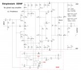
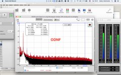
I have balanced the ODNF subtractor in a way that I see the error signal at its minimum amplitude. This signal modulates the VAS load, correcting the errors, produced by the amplifier (especially the ones produced by the OPS).
It's easy to see that the error signal at 20KHz is higher than the one at 1KHz - no surprise, just confirming the amp's distortion rises with frequency increase.
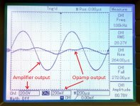
It's also cool to see the error signal at clipping - the error correction circuit tries to "pump up" the output swing.
Although ODNF is a global loop, the nature of its application is very different from the "normal" global feedback - ODNF corrects the errors, regardless of where they are originated, but it does not inject the feedback signal to the input. IPS still runs open loop. Neither magnitude nor phase response (open loop) is influenced by ODNF loop - it only corrects the errors, increasing the overall linearity of the amplifier. Correct me if I'm wrong
In terms of the way it sounds - the nature of the amplifier is rather similar. A proper blind A/B test is required - it's very difficult to hear the difference between no-global-loop and ODNF configurations, as the level of distortion seems to be low enough in both cases, although ODNF is called upon to ensure some 20db distortion reduction.
I still can't measure the spectrums, although this is something I'd love to see. Hopefully, my Audio Analyzer is going to reach me soon - looking forward to checking the harmonic profiles and measure THD /IMD.
Hugh, I find the approach very promising. Highly linear stages with fast local feedbacks, plus some overall error correction seems to give a lot of freedom in design approaches without taking too much care about stability
Same silence at idle.
Nice
Cheers,
Valery


Congratulation Valery, I simulated ODNF some years ago but never built real amp.
Damir
Congratulation Valery, I simulated ODNF some years ago but never built real amp.
Damir
Thank you Damir! Some resistor values within ODNF subtractor required some adjustment in the live prototype. However, in general, the whole thing works pretty much according to my simulation exercises.
I think some of your no-global-feedback circuits (current conveyor) are very suitable for ODNF concept - worth experimenting in this direction
Hi Valery what is the diistortion level of this wave generator?
Hi Thimios, this one has got a relatively high level of distortion - I use it mostly for qualitative (not quantitative) analysis of the circuits' behavior.
The square wave is rather good here though.
Hi Valery,Although ODNF is a global loop, the nature of its application is very different from the "normal" global feedback - ODNF corrects the errors, regardless of where they are originated, but it does not inject the feedback signal to the input. IPS still runs open loop. Neither magnitude nor phase response (open loop) is influenced by ODNF loop - it only corrects the errors, increasing the overall linearity of the amplifier. Correct me if I'm wrong
nice to see such a "non-standard" approach. As we all know, there is no golden way, and much if not all depends on careful dedication to detail.
When speaking about feedback, the common language seems to be "linear systems", but one can possibly accept that as first approximation in the quest for understanding a circuit.
The error amplifier from the figure in post #56 corrects errors made both by IPS and OPS. So, is the IPS in the loop? If you follow the linear systems approach, you can shift the summing point in the figure to IPS input, if you divide the transfer function of error amplifier by transfer function of IPS. Then the error signal sees the same overall transfer function when travelling to the ouptut, as before. Such system transformations are e.g. described in Lurie's book "Classical Feedback Control", repeatedly recommended by forum member jcx (chapter 2 of 2nd edition).
If you now continue to transform the remaining conceptual circuit at the input, the IPS finally seems to be included in the feedback loop. So, if you want to better understand what's going on, a look on available control theory might help. But probably we agree that this is not of prime importance if all works well and the amp does sound nice.
Kind regards,
Matthias
Hi Matthias,
A good point. Well, as Brian (traderbam) correctly noted in the post #58 - as the reference point for ODNF is taken from the very input, the loop is global.
On the other hand, taking into account the point of the error signal injection, this is a combination of the feedback and the feedforward.
We can consider the opamps-based structure as a 2-nd front-end, sitting in parallel with the "main" front-end of the amplifier. Any error, originated in the "main" front-end, is corrected by feeding the correction signal forward to its output - error is subtracted from the (signal + error) at the front-end's output.
From the point of view of OPS (if it ever has one), it's a feedback.
BTW, if I simply short TP2 point to the ground - the amplifier still works with the same amplitude and phase responses, just no error correction is in place (pure no-global-loop operation).
The question we ask ourselves - why do we think we can take that 2-nd opamps-based front-end as a reference circuit for generating the right correction signal? My answer - it works in much "easier" conditions. It operates at much lower swing levels, driving lower loads. It does not necessarily need to be based on the opamps BTW - I'm using this simple ODNF circuit as a proof-of-concept prototype now.
Another cool dependency - the better the main amplifier's linearity is, the less ODNF circuit has to do (lower error signal swing at its output), resulting in the higher overall accuracy. The approach will not work well with some originally "bad" amplifier.
One more important point to mention - I deliberately limit the gain within the ODNF circuit. It does not try to eliminate the error, it just reduces it (roughly -20db, needs to be confirmed by the spectrum measurements).
I'm trying to better understand the theory behind this thing - the project has started from a rather "intuitive" approach, inspired by the Luxman's high-level diagram.
Any ideas are welcome
Cheers,
Valery
A good point. Well, as Brian (traderbam) correctly noted in the post #58 - as the reference point for ODNF is taken from the very input, the loop is global.
On the other hand, taking into account the point of the error signal injection, this is a combination of the feedback and the feedforward.
We can consider the opamps-based structure as a 2-nd front-end, sitting in parallel with the "main" front-end of the amplifier. Any error, originated in the "main" front-end, is corrected by feeding the correction signal forward to its output - error is subtracted from the (signal + error) at the front-end's output.
From the point of view of OPS (if it ever has one
), it's a feedback.BTW, if I simply short TP2 point to the ground - the amplifier still works with the same amplitude and phase responses, just no error correction is in place (pure no-global-loop operation).
The question we ask ourselves - why do we think we can take that 2-nd opamps-based front-end as a reference circuit for generating the right correction signal? My answer - it works in much "easier" conditions. It operates at much lower swing levels, driving lower loads. It does not necessarily need to be based on the opamps BTW - I'm using this simple ODNF circuit as a proof-of-concept prototype now.
Another cool dependency - the better the main amplifier's linearity is, the less ODNF circuit has to do (lower error signal swing at its output), resulting in the higher overall accuracy. The approach will not work well with some originally "bad" amplifier.
One more important point to mention - I deliberately limit the gain within the ODNF circuit. It does not try to eliminate the error, it just reduces it (roughly -20db, needs to be confirmed by the spectrum measurements).
I'm trying to better understand the theory behind this thing - the project has started from a rather "intuitive" approach, inspired by the Luxman's high-level diagram.
Any ideas are welcome
Cheers,
Valery
Attachments
Last edited:
Hi Valery,
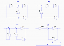
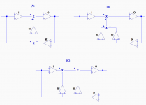
below is the transformation I have in mind. Circuit (A) is the original circuit from post #56. Transfer function of IPS is I, that of OPS is O, E stands for that of error amp, and K for the network from ouptut. Summing points are sketched as "X".
After transformations, one arrives at circuit (D). The right loop there has transfer function G of
G = IO / (1+ IO * KE/I) = IO / (1 + KEO).
When multiplying with the front (1+E/I), one gets the total H of
H = (1 + E/I) G = (I + E) O / (1 + KEO).
The term O / (1 + KEO) is the normal gain of a loop with O in the forward path and KE as NFB path. In front, we have (I + E).
This seems to say that the error amplifier does only correct OPS, and that it is in parallel with IPS.
Cheers,
Matthias
PS. I'll be back on Monday.
Attachments
Valery, you can short TP2 to ground to eliminate the op-amp feedback loop. What would happen if you were to short the original input to ground but still have the input signal to the op-amp? Thus removing the forward gain of the original IPS. How would that sound? (voltage swing limited, of course).
Last edited:
Brian, I've tried to test your suggestion (post 129) in the sim. Phase response is awful, it's unstable - oscillates badly. OK, it's possible to compensate, but then its a very different amplifier with different harmonics profile.
The drawing is close to the design except for the feedback divider. It's also important that IPS at the bottom has got the gain of 29db, set by the local feedbacks inside it.
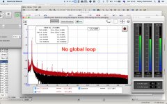
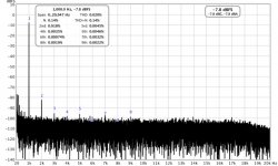
I can't wait for my Audio Analyser to arrive, so I have arranged a qualitative spectrum test, using a compact USB soundcard, designed for serving the headphones and the microphone - that's actually a serious disadvantage of this card as a measurement instrument, but that's what I have in hand right now.
I have no idea about the soundcard performance, plus a high-sensitivity microphone input adds a lot of noise, but we can still see the harmonics profile and the way ODNS suppresses high-order harmonics.
This is 25W output @ 8ohm resistive load.
H2 is reduced by 6db; H3, H5 and H7 - by around 15db - resulting in excellent profile with H2 dominance and rather low higher order components.
More simulations are planned for better understanding the "mechanism" and testing the dependencies.
Matthias - I'm very interested. I still believe the main IPS error is also corrected - need to think a bit more about it.
Cheers,
Valery
The drawing is close to the design except for the feedback divider. It's also important that IPS at the bottom has got the gain of 29db, set by the local feedbacks inside it.
I can't wait for my Audio Analyser to arrive, so I have arranged a qualitative spectrum test, using a compact USB soundcard, designed for serving the headphones and the microphone - that's actually a serious disadvantage of this card as a measurement instrument, but that's what I have in hand right now.
I have no idea about the soundcard performance, plus a high-sensitivity microphone input adds a lot of noise, but we can still see the harmonics profile and the way ODNS suppresses high-order harmonics.
This is 25W output @ 8ohm resistive load.
H2 is reduced by 6db; H3, H5 and H7 - by around 15db - resulting in excellent profile with H2 dominance and rather low higher order components.
More simulations are planned for better understanding the "mechanism" and testing the dependencies.
Matthias - I'm very interested. I still believe the main IPS error is also corrected - need to think a bit more about it.
Cheers,
Valery
Attachments
Something isn’t right.Brian, I've tried to test your suggestion (post 129) in the sim. Phase response is awful, it's unstable - oscillates badly. OK, it's possible to compensate, but then its a very different amplifier with different harmonics profile.
You're right - I used some wrong resistor values for the feedback divider in that simulation by mistake (same ratio, but 10 times higher values). With 33K / 1.3K. as shown in the schematic, stability margins of the error channel are fine - the whole thing works at low swing (roughly 2.8W at the output). No additional compensation required.
Ok. Another thought for you. The IPS effectively boosts the voltage swing of the opamp at the input to the output stage. So it acts like a voltage bootstrap. The IPS also is a transconductance amplifier and its current is sinked by the opamp. So, the IPS does two things: provides wider voltage swing and modulates the output current of the opamp. With the IPS input grounded, the opamp is not current modulated.
The error amplifier from the figure in post #56 corrects errors made both by IPS and OPS. So, is the IPS in the loop?
Hi Valery,Matthias - I'm very interested. I still believe the main IPS error is also corrected - need to think a bit more about it.
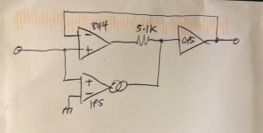
on first sight, the scheme looks like providing some kind of forward error correction for the input stage. But below is a further, much simpler, argument without any calculations for the seemingly counter-intuitive result from post #128.
Food for thought.
Cheers,
Matthias
Attachments
Better spectrum measurement
I have managed to improve the soundcard grounding, getting the spectrum closer to reality. The measurement system is still suboptimal - I'm using a mic input, producing a lot of noise. Anyway, the profile is good, as well as the level of harmonics. The amplifier is very comfortable for a long listening at the relatively low volumes, including near-field listening (a-la studio monitors).
I have managed to improve the soundcard grounding, getting the spectrum closer to reality. The measurement system is still suboptimal - I'm using a mic input, producing a lot of noise. Anyway, the profile is good, as well as the level of harmonics. The amplifier is very comfortable for a long listening at the relatively low volumes, including near-field listening (a-la studio monitors).
Attachments
Ok. Another thought for you. The IPS effectively boosts the voltage swing of the opamp at the input to the output stage. So it acts like a voltage bootstrap. The IPS also is a transconductance amplifier and its current is sinked by the opamp. So, the IPS does two things: provides wider voltage swing and modulates the output current of the opamp. With the IPS input grounded, the opamp is not current modulated.
That's true to some extent. However, if we see the main IPS and the error channel IPS as two IPSs in parallel - their role is still very different.
The main IPS provides the required voltage swing - true, it also forms the amplitude and phase responses as a function of frequency, ensuring proper stability margins of the whole amplifier.
The signal at the output of the opamp section is an error signal - a difference between the input and the output signals, with the amplitudes being aligned by the feedback divider. It's a helper signal, its waveform is rather "corrupted", as it reflects the distortion, its magnitude is 600 times (55.6 db) lower than the output signal's magnitude.
Although the error channel employs NFB from the very output, it changes neither amplitude nor phase response of the amplifier - bode plot is the same with ODNF on, or ODNF off.
Also, if I just arrange a "traditional" NFB, connecting the divider directly to the resistor network at the IPS's sources, the bode plot will change and we will have a different harmonic profile.
What I'm trying to say - ODNF mechanism, although it employs NFB, is significantly different from the way a "normal" global loop works.
Attachments
Hi Valery,
on first sight, the scheme looks like providing some kind of forward error correction for the input stage. But below is a further, much simpler, argument without any calculations for the seemingly counter-intuitive result from post #128.
Food for thought.
Cheers,
Matthias
I have tested this in the simulation - I have replaced D1 and D2 diodes in the IPS's current mirrors with resistors so that those mirrors are not the mirrors anymore. DC balance of the circuit is the same, but harmonic distortion is much higher. As soon as I balance the error channel, the overall level of distortion is 20 db down - error correction corrects the error in IPS as well as the one in OPS (error signal waveform at the output of the opamp is much more complicated in this case).
In terms of common sense - I see it in a way that the error in the IPS appears at the output. As soon as an error signal is "crystallized", it contains an overall error, including the one from the IPS. Being injected into the signal path, it corrects the overall error (it's ok that it's injected at the front-end's output - correction works anyway).
Let's think a bit more
Would you post the simulated feedback loop bode plot?What I'm trying to say - ODNF mechanism, although it employs NFB, is significantly different from the way a "normal" global loop works.
Hi Valery,I have tested this in the simulation - I have replaced D1 and D2 diodes in the IPS's current mirrors with resistors so that those mirrors are not the mirrors anymore. DC balance of the circuit is the same, but harmonic distortion is much higher. As soon as I balance the error channel, the overall level of distortion is 20 db down - error correction corrects the error in IPS as well as the one in OPS (error signal waveform at the output of the opamp is much more complicated in this case).
this is a good idea. (Did something similar in my current design in order to understand distortion correction mechanism.) But what do you mean by "balance the error channel"?
That was also my view at the beginning, and somehow it still appears as very reasonable.In terms of common sense - I see it in a way that the error in the IPS appears at the output. As soon as an error signal is "crystallized", it contains an overall error, including the one from the IPS. Being injected into the signal path, it corrects the overall error (it's ok that it's injected at the front-end's output - correction works anyway).
For sure!Let's think a bit more
Cheers,
Matthias
- Home
- Amplifiers
- Solid State
- No-global-loop amplification