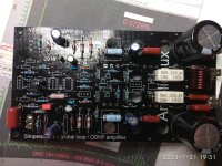
I've managed o get back to doing some testing on the AX-3 amp. I tested with +/- 56VDC supplies. It's very well behaved and clips nicely at 150W output. Surprisingly with a dozen output devices it doesn't generate a lot of heat on the scrap metal heat sink I'm using so I should be able to thrash it harder. I'll have to figure out where I put my high voltage supplies.
Attachments
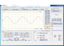
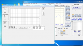
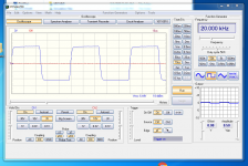
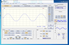
As Valery suggested it's running with OPA2134. My current test speakers in the lab are pretty much embarrassing but the amp sounds good with no sign of hum or hiss when playing through them. Next on the list is to design some power supplies for these monsters and test a new concept in protection system for it.
Hello,
I've been looking for another amplifier for my speakers that can take more than 10W continuous power for a while now. The home-built amps I have play something like what is described here. Through their development I know the value of paired jFET. Since these jFETs are hard to get, I have a question: can I use BJTs like Diotec ZTX458 and ZTX558 as inputs in the SIMPLESTARK circuit? These are supposed to be very low noise and offer a potential to work relatively linear.
What do you think Valery?
Hello Valery,
I have researched the components for your amplifier, they are not so easy to get - as I have already written about the JFET.
You have already studied the Dartzeel circuit, as you wrote. Since the servo circuits for the adjustment of the DC offset are rather unfunctional for me with respect to their function, regarding a non-linear correction of the characteristic diagrams of the transistors, I think it is a good idea to apply the ODNF designed by you also to the Dartzeel circuit.
What do you think about the idea to influence the Dartzeel circuit after the second amplifier stage, i.e. before the resistors R21 and R22, via the ODNF?
Another question: Have you already tried the OP1611 for the ODNF? I would want to give it a high "musicality".
Regards Tim
Hello Valery,
I have researched the components for your amplifier, they are not so easy to get - as I have already written about the JFET.
You have already studied the Dartzeel circuit, as you wrote. Since the servo circuits for the adjustment of the DC offset are rather unfunctional for me with respect to their function, regarding a non-linear correction of the characteristic diagrams of the transistors, I think it is a good idea to apply the ODNF designed by you also to the Dartzeel circuit.
What do you think about the idea to influence the Dartzeel circuit after the second amplifier stage, i.e. before the resistors R21 and R22, via the ODNF?
Another question: Have you already tried the OP1611 for the ODNF? I would want to give it a high "musicality".
Regards Tim
what is the Uniqueness of OPA1611 when compared with OPA2132?
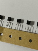
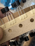
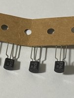
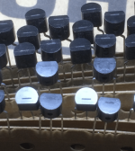
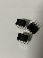
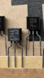
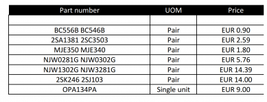
Simpelstark amplifier rare components are available in addition to other components.
All components are 100% genuine no fakes.
Anyone interested please PM, there will be a fixed shipping fee of $25 via DHL or FEDEX & 5.5% PayPal fees.
Thanks
All components are 100% genuine no fakes.
Anyone interested please PM, there will be a fixed shipping fee of $25 via DHL or FEDEX & 5.5% PayPal fees.
Thanks
| BC556B BC546B |
| 2SA1381 2SC3503 |
| MJE350 MJE340 |
| NJW0281G NJW0302G |
| NJW1302G NJW3281G |
| 2SK246 2SJ103 |
| OPA134PA |
Attachments
Hi to all of you.
I wish a happy New Year!
Resently i'm in troubles with my Simpelstark.
Protection activieted as a result of 4v d.c offset.
I come to the conclusion that the problem is due to the input pair.
The fact that the input fet class is not specified adds a difficulty too.
I would be very happy if anyone can recognize and analyze the input stage topology.
Attachments
Hi Jeff,i have measured across R9,R14.where are you measuring the current flow in the input stage?
Using 2SK246-J103 Y grade VR9=1.4V IR9=VR9/R9=1.4/560=2.5mA
VR14=1.4V I=2.5mA
VAS current across R22.R23 VR22=1.4V IR22=VR22/R22=1.4/220= 6.3mA
Using 2SK246-J103 GR grade VR9=1.9V IR9=VR9/R9=1.9/560=3.3mA
VR14=1.9V 3.3mA
VAS current across R22.R23 VR22=1.9V IR22=VR22/R22=1.9/220=8.6mA
Using 2SK246-J103 BL grade VR9=4.4V IR9=VR9/R9=4.4/560=7.8mA
VR14=4.4V 7.8mA
VAS current across R22,R23 VR22=4.4V IR22=VR22/R22=4.4/220=20mA
Power Supply=+/-45V
Yes,i beleive Y would be the right grade.From your measurements it looks like y grade are the correct fets. Valery usually designed inputs to operate around 2.5mA and VAS to run between 5 - 7 mA
Unfortunately i have two pieces only...
Is it posible to use GR grade lowering the value of R9,R14?
Because i have the pcb,a lot of parts,some unused original latfets,i manage to start this.
Now i see that some parts on the pcb not in schematic...like C20,C21,R40.
I think that is time to ask for help.
Please Jeff can you have a look?
What is the schematic that match this ver.1.2 pcb?
thimios
Now i see that some parts on the pcb not in schematic...like C20,C21,R40.
I think that is time to ask for help.
Please Jeff can you have a look?
What is the schematic that match this ver.1.2 pcb?
thimios
Attachments
- Home
- Amplifiers
- Solid State
- No-global-loop amplification