The Opamp I pulled out of my carver M1.0t had 9 pins instead of 8 as per the datasheet.
But carver 1.0 manual says 9 pins for IC101, figured 1 and 8 are not used.
So, Ok tested it with the transitor tester and this is what I got.
2,3,4 = BCE, NPN, Hfe=2 (sometimes 3) and Vf=1320 mv.
5,6,7 = BCE, NPN, Hfe=2-3 and Vf=829 mv.
What does that indicate ? and what else should I measure. Maybe I should check the other 3 to see if one of em is shorted to one of these ... etc etc ?
Thanks.
Srinath.
figured 1 and 8 are not used.
No, it is just the same as the 8-DIP pins 1 through 8, except those functions are now pins 2-9. Pin 1 is internally connected to pin 9. In other words, if you have a 9 and snip off pin 1, you can stick it on place of an 8. Put pin 2 in the pin 1 spot, etc.
Having pins 1 and 9 connected allows one to feed V+ into pin 9 at one end and then out pin 1 at the other to go to the next IC. In some boards that is a convenience to the designer.
Here: I do not recommend NTE parts, but their data sheet shows the internal connections
http://www.nteinc.com/specs/1500to1599/pdf/nte1529.pdf
If you are replacing a 9-pin with an 8, look to see if pin 1 is even wired. If it is needed, run a jumper over from the other end and stick an 8 in there in 2-9.
The Opamp I pulled out of my carver M1.0t had 9 pins instead of 8 as per the datasheet.
But carver 1.0 manual says 9 pins for IC101, figured 1 and 8 are not used.
So, Ok tested it with the transitor tester and this is what I got.
2,3,4 = BCE, NPN, Hfe=2 (sometimes 3) and Vf=1320 mv.
5,6,7 = BCE, NPN, Hfe=2-3 and Vf=829 mv.
What does that indicate ? and what else should I measure. Maybe I should check the other 3 to see if one of em is shorted to one of these ... etc etc ?
Thanks.
Srinath.
Opamps contain transistors but can not be tested as a 'transistor'. Your measurements are meaningless. Your 9 pin chip is a Single Inline Package (SIP). The typical through hole opamp is an 8 pin Dual Inline Package (DIP). DIP opamps are very common, SIP are not common.
In general, opamps rarely fail so what has you 'checking' opamps this way? The best way to 'test' is to observe if they are operating properly. Almost always the '+' and '-' inputs and the output will have nearly the same DC levels (a few milliVolts diference). There are circuits that may end up with a very different level on the output compared to the inputs but these are not common.
G²
This is a carver m1.0t I started to modify, but all I did at this point was a recap of small electrolytic caps.
I bent the board the SIP opamp was installed on pretty much right at the location of the opamp during a recap. It stayed bent for a few hours.
The amp itself started working, and after a few mins, would cut out. Then a few min later work, and repeat, working for less and less time and staying dead for longer and longer.
Then finally it went dead. I noticed its not really dead, it just has about 2 watts of power, instead of 200. At full volume on the preamp its just about audible. Essentially its acting just if there was no gain from this opamp.
So in effect, my next question is - is that Hfe of 2 indicative of something - and is it bad.
Thanks guys.
Srinath.
As has already been pointed out, you can not test IC's with a component tester. Not only can you not do so, with any results having no relevance, there is also the distinct possibility of the component tester impairing the characteristics of the device under test as it can reverse bias highly sensitive internal junctions in just the same way that testing certain transistors with a DVM can permanently degrade the noise figure of the device.
Enzo: You are right - 9 is shorted to 1 in the board.
Mooly: Thanks, that was what stratus46 said, but sometimes 2-3 times is what it may take ... sometimes never.
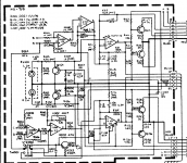
I have a similar question then - The preamp and the whole thing circuits are below.
I am supposed to feed a .5 v P-P 1Khz signal via the RCA inputs and read 10v P-P at pin 2 of this opamp.
I dont have a signal generator and I dont have anything very sensitive to read .5v P-P. So I took a receiver and put the rca's in the tape monitor out. The P-P read on the rca's read about .1v on my multimeter. The output from pin 2 of this opamp in the circuit read .2. Logically I should have got 2v (I would think). I then puleed the opamp and tested it.
Given the thing did that, is it possible its bad.
Thanks.
Srinath.
Mooly: Thanks, that was what stratus46 said, but sometimes 2-3 times is what it may take ... sometimes never.
I have a similar question then - The preamp and the whole thing circuits are below.
I am supposed to feed a .5 v P-P 1Khz signal via the RCA inputs and read 10v P-P at pin 2 of this opamp.
I dont have a signal generator and I dont have anything very sensitive to read .5v P-P. So I took a receiver and put the rca's in the tape monitor out. The P-P read on the rca's read about .1v on my multimeter. The output from pin 2 of this opamp in the circuit read .2. Logically I should have got 2v (I would think). I then puleed the opamp and tested it.
Given the thing did that, is it possible its bad.
Thanks.
Srinath.
Attachments
The feedback network around the opamp is complex with three returns and relies on the amp as a whole working. R113 at the top and R011 all have an effect. I doubt the opamp was ever faulty tbh, they are extremely reliable, but whether it has suffered as a result of testing is another matter. Make sure the muting transistors are off.
Its only 5 minutes work to fit an 8 pin DIL one to test it by substitution. One side will fit the board direct and the other side needs hard wiring.
Its only 5 minutes work to fit an 8 pin DIL one to test it by substitution. One side will fit the board direct and the other side needs hard wiring.
I bent that board with the crest of the bend right where the opamp is. Reliable electrically isn't quite the same as being mechanically damaged. OTOH - I seems to work. Albeit weakly.
R113 and R011. I'll check those.
Now what are the muting transistors ? This amp makes a loud hum without this opamp installed.
Thanks.
Srinath.
R113 and R011. I'll check those.
Now what are the muting transistors ? This amp makes a loud hum without this opamp installed.
Thanks.
Srinath.
The muting transistors are those on the input sockets. Don't remove them, just measure the base voltage. It should be negative by a small amount. If its +0.6 or higher then there is something causing it to mute.
The feedback resistors wont be faulty either... what I am saying is that how they interact with the rest of the circuit as a whole determines the gain.
The feedback resistors wont be faulty either... what I am saying is that how they interact with the rest of the circuit as a whole determines the gain.
DIP opamps are very common, SIP are not common.
SIPS are very common in commercial grade equipment of a certain vintage. I see them all the time, and you can still get some replacements in a SIP package.
I used to have a yamaha cd player with a SIP opamp, I wish I hadn't traded it away.
I still may go through my storage and dig some cd players or and see if I cant find one of these to harvest. I also have to test the other stuff and order them all in 1 sweep from mouser.
Cool.
Srinath.
I still may go through my storage and dig some cd players or and see if I cant find one of these to harvest. I also have to test the other stuff and order them all in 1 sweep from mouser.
Cool.
Srinath.
As has already been pointed out, you can not test IC's with a component tester. Not only can you not do so, with any results having no relevance, there is also the distinct possibility of the component tester impairing the characteristics of the device under test as it can reverse bias highly sensitive internal junctions in just the same way that testing certain transistors with a DVM can permanently degrade the noise figure of the device.
That is an interesting bit of information.
Oh, may be relevant - no idea -
At one time in the circuit below c102 was touching - or was too close to 1 side of R106 - eyeballing it a few seconds - may have not touched - but may have. It may have been there before I got it, or after when I was handling the board etc etc - no idea.
But I have separated them a while ago and the problem remains.
Cool.
Srinath.
If R102 were a jumper then the circuit would be trying to mute by applying a short (via the conducting transistor) across the input directly. Not good and not effective, and it also removes the protection afforded by the resistor if a source component with a DC offset were connected. R106 is needed for the RF filter to work (the 120pf cap connected to it)
So If R106 was a jumper I'd have RF in the signal. OK I didn't get much hiss or static type sound - I guess that wasn't happening.
If R102 were a jumper it will mute the signal ... and fail, and mute it again and fail ? (cos you said not effective)
That was how this amp sounded before it went the dodo way. It now makes very little power. Like full volume sounds like 2 watts.
Is it possible the R102 turning into a jumper killed Q102 ? But then why is it affecting both channels ?
Thanks.
Srinath.
You are not understanding ")
I asked you to measure the voltage on the base of the muting transistors because they are driven together. The base drive to those affects both channels. If they are conducting then the input signal is almost shorted out. It was something worth checking.
The other things, R102 and R106 and so on are just questions you asked. Those parts won't be faulty. R102 and R106 are in series with the input signal and form a filter with the addition of the 120pf cap. Those values stop RF from entering the amplifier (they have a -3db point 230kHz). Your fault lies elsewhere...
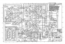
Have you measured the basics... that all the supplies are correct. There are a lot of auxiliary rails in this amp. Look at the power supply and check that all the supplies are correct.
I asked you to measure the voltage on the base of the muting transistors because they are driven together. The base drive to those affects both channels. If they are conducting then the input signal is almost shorted out. It was something worth checking.
The other things, R102 and R106 and so on are just questions you asked. Those parts won't be faulty. R102 and R106 are in series with the input signal and form a filter with the addition of the 120pf cap. Those values stop RF from entering the amplifier (they have a -3db point 230kHz). Your fault lies elsewhere...
Have you measured the basics... that all the supplies are correct. There are a lot of auxiliary rails in this amp. Look at the power supply and check that all the supplies are correct.
I started with a nice working m1.0t. The small electrolytics were replaced with identical values except in cases where they were replaced with higher voltage units cos the am will be run @ 112v out of the transformer instead of 100 - but I'm getting ahead of where I am now - so far, small caps have been replaced. This board was bent while installed and here I am.
The board was bent in a small bow cos the replacement caps were too tall and I screwed it in not realising that and bent the board. However the caps have been replaced to the originals and board is no longer bent.
I played it for a good 20 min, and it worked great except for the periods of cutting out which got worse and worse till it now is where its got no gain.
I'll measure the voltages at the base of the muting transistors - and I have to put the njm072 back in the board right ? So Base of q101 and 102. I'll check and post back.
Thanks Mooly.
Srinath.
- Status
- This old topic is closed. If you want to reopen this topic, contact a moderator using the "Report Post" button.
- Home
- Amplifiers
- Solid State
- NJM072 opamp question