Hello to everyone after sometime!
This tuner had above average sound in terms of low distortion and level of detail represented, so I think it is worth to spent some time to repair it and have all day listener.
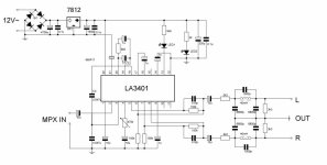
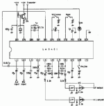
I have checked reference zero voltage on the Sumida Discriminator Coil for Sanyo LA1235, between point marked x and TP1. it is 0.045 mV. There is no deference with trimming pot for muting threshold and nothing happens when I touch front end ceramic filters both with level of mono output or getting stereo signal. At one moment I have measured 19Khz pilot signal on the LA 3401 FM MPX demodulator IC.
Discriminator coil pots are blocked, there is a cracking sound til switching mute and narrow/wide band and sometimes output level gradually goes low.
After switching wide/narrow band output level comes back on on the same level which is also low.
What to measure next?
This tuner had above average sound in terms of low distortion and level of detail represented, so I think it is worth to spent some time to repair it and have all day listener.
I have checked reference zero voltage on the Sumida Discriminator Coil for Sanyo LA1235, between point marked x and TP1. it is 0.045 mV. There is no deference with trimming pot for muting threshold and nothing happens when I touch front end ceramic filters both with level of mono output or getting stereo signal. At one moment I have measured 19Khz pilot signal on the LA 3401 FM MPX demodulator IC.
Discriminator coil pots are blocked, there is a cracking sound til switching mute and narrow/wide band and sometimes output level gradually goes low.
After switching wide/narrow band output level comes back on on the same level which is also low.
What to measure next?
Attachments
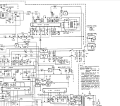
Those measured points are actually before and after r121 6.8kOhm on the Nikko or resistor 4.8Kohm from the schematic from LA1235 data sheet attached? It is important to know in order to eliminate misalignment od discriminator coil. | ||


| 


|

|
 Quick Reply
 |
Message: |
Attachments
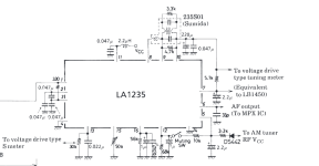
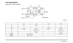
| Voltage on the pins of LA1235 muting off, mono output signal is present with attenuation: 1-3. 3V, 4-5. 0V, 6. 1.9V, 7. 11.9V, 8-10 6.3V 11. 13.5V 12. 6.25V, 13. 3.1V, 14. 0V 15. 6.8V, 16. 3.45V There is a change on the base of tr101 and 104 from 0V-1.8V when switching wide/narrow while switching mono mute off/on gives no change. Also switching W/N causes crackling output and gives signal back after occasionally fading. Sometimes there is a crackling sound from the board like relay, when touching with probe TP1 point. I will check switches. | |
|
|
|
|
|
Quick Reply | |||||||||||||||
Message:
Options |


![Wrap [QUOTE] tags around selected text](https://www.vintage-radio.net/forum/images/editor/quote.gif "Wrap [QUOTE] tags around selected text")


| Sorry, my mistake,checked everything again. TP voltage has to be measured on to r121, for sure and it is 5.4V away from zero volts. Also, voltage on the pin 6 should be 6.5V instead of 1.8V. Does someone knows values of caps insde the Sumida Discriminator Coil for Sanyo LA1235 FM IF Circuit, have this part or idea how to wind it manualy? It is so much far from reference, so I will put some caps between pins 8 and 10 in parallel to cap inside discriminator. | |
|
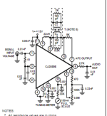
he value of parallel cap inside IF coil for CA3089 is 100pF.
I am measuring infinite capacitance here, so this might be the cause of excessive voltage over 0V on the TP1. Does someone has opened such coils?
I will open coil and cut connection of that cap, there is no point to examine further before fixing this fault.
In one moment til measuring voltage changes around reed relay that switches output signal, one probe only once was strongly attracted by it. Not sure is it working properly, that crackling during switching wide-narow should not be present as occasionally attenuation of output signal.
It is ferrite dust type core. I can see small shinning particles.
Electrolytic caps seems OK.
Attachments
Aligning FM radios is difficult and requires special test equipement. I would not monkey with coils or pots. I have found some success by replacing all those electrolytic caps, especially the 1 to 3 uf ones, with new ones. I used CPO ceramic for those values. I would replace the 100 and 220 uf ones also with aluminum electrolytic caps. No alignment was required on a 1978 Reader's Digest AM/FM receiver. Sensitivity went back to where it was when my Father bought it. Stability was certainly better than the Craig pocket radio I bought 2 years ago. That piece of trash required retuning every minute. I also pepped up the FM of a Luxor cassette deck+AM/FM about 1990, by replacing e-caps also.
Last edited:

Thanks. I have already buy el caps but this infinite capacitance in IF coil has to be resolved.
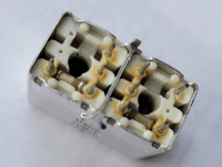
Here is the picture from the bottom of similar IF coil from the net.
I would say that this two same elements are caps in IF coil. There is only one small extra coil in addition to the two ordinary coils.
Schematic diagram is for similar IF coil but wit two smaller coils.
Here is the picture from the bottom of similar IF coil from the net.
I would say that this two same elements are caps in IF coil. There is only one small extra coil in addition to the two ordinary coils.
Schematic diagram is for similar IF coil but wit two smaller coils.
Attachments
Last edited:
Aligning FM radios is difficult and requires special test equipement. I would not monkey with coils or pots. I have found some success by replacing all those electrolytic caps, especially the 1 to 3 uf ones, with new ones. I used CPO ceramic for those values. I would replace the 100 and 220 uf ones also with aluminum electrolytic caps. No alignment was required on a 1978 Reader's Digest AM/FM receiver. Sensitivity went back to where it was when my Father bought it. Stability was certainly better than the Craig pocket radio I bought 2 years ago. That piece of trash required retuning every minute. I also pepped up the FM of a Luxor cassette deck+AM/FM about 1990, by replacing e-caps also.
Changed cap 114, pin 8, no more fading out, but voltage remains out of specs 1.8V and have reading double capacitance of new cap soldered on the board . I was suspicious about oscillating. No stereo signal yet.
I have made a mistake, it is cap 114 on the pin 6.
It is nice mess with caps leakage regarding temperature change and opportunity to explain implementation of LA 1235 and finally have reference voltages here.
I am measuring 0.9V between pins 9 and 10 on the r120 where is cap inside IF coil connected in parallel.
Touching TP2 and points that are connected to the IF coils, causing backing output signal to the full level, so maybe there is oscillation too.
After changing cap 114, sensitivity has go lower.
I will be grateful for ideas how to improve original circuit too.
Measured voltages on the LA1235:
1-3. 3V,
4-5. 0V,
6. 1.9V,
7. 11.9V,
8-10 6.3V
11. 13.5V
12. 6.25V,
13. 3.1V,
14. 0V
15. 6.8V,
16. 3.45V
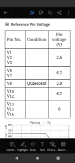
Part of reference voltages from LA1235 data sheet is on the picture.
It is nice mess with caps leakage regarding temperature change and opportunity to explain implementation of LA 1235 and finally have reference voltages here.
I am measuring 0.9V between pins 9 and 10 on the r120 where is cap inside IF coil connected in parallel.
Touching TP2 and points that are connected to the IF coils, causing backing output signal to the full level, so maybe there is oscillation too.
After changing cap 114, sensitivity has go lower.
I will be grateful for ideas how to improve original circuit too.
Measured voltages on the LA1235:
1-3. 3V,
4-5. 0V,
6. 1.9V,
7. 11.9V,
8-10 6.3V
11. 13.5V
12. 6.25V,
13. 3.1V,
14. 0V
15. 6.8V,
16. 3.45V
Part of reference voltages from LA1235 data sheet is on the picture.
Attachments
I have swapped out IF coil and capacitance of inside capacitor is 50pF, voltage on the pin 6 is now 3.5V instead of 1.8V, there is no more short between pins 8 and 9 and there is no output signal while signal meter shows full strength.
On the outside pins of IC coil I cannot find points where I can measure that 50 pF, so it is likely damaged and I will order another one. It is too sensitive and fragile to play with it.
On the outside pins of IC coil I cannot find points where I can measure that 50 pF, so it is likely damaged and I will order another one. It is too sensitive and fragile to play with it.
I have put back IF coil back and get mono output only, while voltage on the pin 6 has stayed higher 3.6V compared to previous 1.8V.
Voltage on the TP2 is still dead on 5.6V
I have also changed main PS cap and few more, so in order to know what I am doing it is necessary to change them all.
There is a something like wax in the IF coil slug and on some places I can see tiny wire.
Is there proceed for safety turn it?
Voltage on the TP2 is still dead on 5.6V
I have also changed main PS cap and few more, so in order to know what I am doing it is necessary to change them all.
There is a something like wax in the IF coil slug and on some places I can see tiny wire.
Is there proceed for safety turn it?
adason, I really think his FM detector is so far off that he probably doesn't have any composite audio or pilot tone coming out from that LA1235. He said the slug in T102 was stuck - I'm afraid if he tries too hard to turn it it will break.
He has aother thread on this here: https://audiokarma.org/forums/index...uner-no-stereo-low-level-mono-output.1055234/
He has aother thread on this here: https://audiokarma.org/forums/index...uner-no-stereo-low-level-mono-output.1055234/
No, i said trimmer. Pin 4 trimmer.Thanks, do you mean to gently turn the slug on the IF coil?
But Ylli may be right.
Attachments
7. 11.9V,
8-10 6.3V
11. 13.5V
Those voltages seams higher, thus LA1235 is hotter than other ICs.
That composite audio and pilot signal is for decoding stereo in next IC and I have measured earlier that 19kHz, but with just basic function for frequency counter.
Pin 7 is on the VC FM rail that comes from front end.
I am wondering why output audio goes to normal level when I touch pin 8?
.
There is no trimmer here on the pin 4 LA3401.No, i said trimmer. Pin 4 trimmer.
I am measuring 17.5kOhm R121 what could be explanation to have that 5.6V across, what is TP2 reference voltage.
In the service manual R121 is listed twice, with 6.8kOhm and 18kOhm.
I did not find any trace of earlier repairing attempt, so is that doubled values is for different IF coils?
In the service manual R121 is listed twice, with 6.8kOhm and 18kOhm.
I did not find any trace of earlier repairing attempt, so is that doubled values is for different IF coils?
Attachments

Svetoklik, where are you? R121 is listed twice because it's value is different depending on whether this is a USA/Canada (W) or European (E) model. In the USA/Canada, R121 is 6.8K, in the European model, R121 is 18K.

While troubleshooting the LA1235, the only test points you should be looking at are the ones between T102 and R121. The layout in the manual calls this TP1.
While troubleshooting the LA1235, the only test points you should be looking at are the ones between T102 and R121. The layout in the manual calls this TP1.
- Home
- Source & Line
- Analogue Source
- Nikko NT 950 Tuner, no stereo, low level mono output signal