Hello,
I just registered and I am so happy to find this forum.
I am 22 and trying to build my first tube amp.
Hope that I can add some questions here.
I am building a push pull 6550 power amp with cathode bias. It looks that could be work.
My first question is.
I am measuring about the double AC current before rectification compared with the total cathode DC currents.
Why is that?
thank you so much
Post your schematic here. This should help:
https://www.hammfg.com/electronics/transformers/rectifier
https://www.hammfg.com/electronics/transformers/rectifier

atreas2,
Welcome to diyAudio.
Wow! Jumping in with both feet, push pull 6550 for your first amplifier.
Power Supplies:
A B+ Capacitor Input Filter can have peak currents that are up to 10 times the DC load current.
Even though the peak current time is narrow, the integrated RMS current can be 2 x the DC Load Current.
Caution: if you order a power transformer, and you [insist] on using a Capacitor Input filter for the B+, then be sure to select the correct transformer.
Example, suppose you need a DC load current of 100mA, be sure that the power transformer's B+ secondary is rated for 2 X 100mA = 200mA.
Push pull amplifiers that run class AB, during medium and maximum signal output, often have integrated DC load current that is much larger than the quiescent DC load current.
Single ended amplifiers have a relatively constant DC load current, from quiescent to maximum (unclipped) power output.
Hint: Want a cool running power transformer, then select a higher voltage B+ winding rating, and use a choke input B+ filter.
The voltage loss of the choke input filter is 0.9 x the secondary Vrms.
Do not forget to account for the additional voltage losses from the choke DCR, and the tube rectifier. If you use solid state diodes, the voltage loss of the diodes is very small compared to a tube rectifier.
Last edited:
I am trying to figure out this difference. Since I have 82mA DC on each of two cathodes but 330mA AC before rectifier, with no other load or driver tubes connected
What kind of power supply do you have? FW, FWCT, capacitor input, choke input, etc.
The secondary AC current will be different in each case, even if the output stage DC current is adjusted
to be 164mA in all cases.
Also plain vanilla multimeters show correct RMS values only for pure sinusoidal currents.
But the waveform of the current between transformer secondary and rectifier is not a sinus at all if the rectifier feeds into a capacitor.
Because the diodes only conduct during the short periods of time when the momentary AC voltage is higher than the DC.
But the waveform of the current between transformer secondary and rectifier is not a sinus at all if the rectifier feeds into a capacitor.
Because the diodes only conduct during the short periods of time when the momentary AC voltage is higher than the DC.
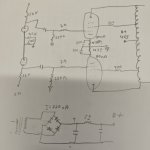
You have a full wave bridge rectifier, with a capacitor input filter. According to the Hammond paper linked above,
divide your DC load of 0.160A by a factor of 0.62 in order to get the secondary AC current of 0.26A.
This is close enough to your measured 0.33A secondary AC current, considering the likely meter error, which could be substantial.
Most cheap meters cannot measure true Vrms anywhere near accurately enough.
But how are you measuring it & what are you measuring and with what meter? If you use a meter as an ammeter are you measuring surge, peak or RMS current?Hello and thank you for your answers. I am still trying to learn. I am measuring 330mA AC before bridge
80mA x 470r should give you about 37v on the 6550 cathodes. Therefore that's a total of about 160mA of HT current, so AC quiescent current cannot be 330mA. Try measure across a 10 ohm resistor between the first capacitor and second capacitor.
The Peak AC current to the first filter capacitor can be Several Times Larger, versus the DC load current.
Also, the Peak AC current is Several Times Larger versus the ACrms current.
Where did you measure the AC current?
On what model meter?
Etc.?
There is a reason for why you get what you got; It only requires a little research to find out the why.
A complete and accurate schematic of the power supply that includes the parts values, is worth:
1000 Words
And . . .
20 un-needed extra Posts.
- Home
- Amplifiers
- Tubes / Valves
- Newby Push Pull Question