Hi, I thought I should put this up on behalf of people like myself who have a go at a diy build but don't have a full understanding of what they are doing so I apologise if all the brains here are now sighing. If your green read on.If you have the brain the size of a planet don't bother any further.
There is a possible danger in the lampizators pdf explaining how to build his srpp output stage for dacs/cd players. Now I wont put the image up incase I am breaking the law.So will explain.
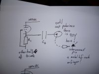
If you look where he shows to take the output which will go to a preamp or say volume pot or tripath amp etc. You will see he uses a 4uf to 10 uf DC blocking capacitor. This is because the music signal will be mixed up with high voltage DC!!!!!So we want to remove the dc so the next stage of our hi fi gets just the music signal and does not fry with the high voltage DC. But here hides a danger.
He shows just the capacitor wired in series from the first cathode to the RCA plug. The RCA centrepin and therefore an interconnect cable plug (if not pluged into the other hifi unit) will be live with 90vollts DC because it takes a few minutes for the capacitor to polarise enough to eventually block the dc. SO!!! A situation could arise where you turn on your lampizator and in your haste have forgotten to connect the other end of your interconnect and you touch the hot pin !!!!OR that plug is resting on a metal table!!!
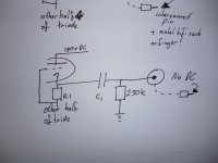
To stop this you need to wire in a 50K to 1M resistor so the capacitor polarises instantly. I could not figure out what value I liked as the value affects the sound.I ended up putting a tripath in the same chassis as the srpp so there are no interconnects and I rely on the volume pot of the tripath to polarise the blocking capacitor. Hope my photos give a clearer picturer as I am not good with words.
This is not meant to slag off the Lampizator in any way. He has gone to massive massive efforts to educate people about valves, and every question I have ever aked him he has taken the trouble to answer.
There is a possible danger in the lampizators pdf explaining how to build his srpp output stage for dacs/cd players. Now I wont put the image up incase I am breaking the law.So will explain.
If you look where he shows to take the output which will go to a preamp or say volume pot or tripath amp etc. You will see he uses a 4uf to 10 uf DC blocking capacitor. This is because the music signal will be mixed up with high voltage DC!!!!!So we want to remove the dc so the next stage of our hi fi gets just the music signal and does not fry with the high voltage DC. But here hides a danger.
He shows just the capacitor wired in series from the first cathode to the RCA plug. The RCA centrepin and therefore an interconnect cable plug (if not pluged into the other hifi unit) will be live with 90vollts DC because it takes a few minutes for the capacitor to polarise enough to eventually block the dc. SO!!! A situation could arise where you turn on your lampizator and in your haste have forgotten to connect the other end of your interconnect and you touch the hot pin !!!!OR that plug is resting on a metal table!!!
To stop this you need to wire in a 50K to 1M resistor so the capacitor polarises instantly. I could not figure out what value I liked as the value affects the sound.I ended up putting a tripath in the same chassis as the srpp so there are no interconnects and I rely on the volume pot of the tripath to polarise the blocking capacitor. Hope my photos give a clearer picturer as I am not good with words.
This is not meant to slag off the Lampizator in any way. He has gone to massive massive efforts to educate people about valves, and every question I have ever aked him he has taken the trouble to answer.
Attachments
The RCA centrepin and therefore an interconnect cable plug (if not pluged into the other hifi unit) will be live with 90vollts DC because it takes a few minutes for the capacitor to polarise enough to eventually block the dc. SO!!!
A capacitor blocks DC at any time, no cap needs "minutes" to "polarize". What happens is that the cap has to charge at the beginning, but the current to charge such a small cap will be very small. You might be reading a voltage at the plug with a high-resistance DMM, but I seriously doubt that the charging of the cap presents any security issue.
Greetings,
Andreas
No I not been zapped. I built one for a friend and was checking everything like mad because I wanted to make sure everything was safe. Imagine if you caused someone to have a shock! And I had seen a similar thing happen when I tried building a transistor spdif buffer, with just the cap I had dc in the signal.
Like I stress this post is for people like me, who don't truely understand about electronics but have a go because of all the things they read about the sound
Like I stress this post is for people like me, who don't truely understand about electronics but have a go because of all the things they read about the sound
well, I got to tell you it does not because, I found this out not by deduction, I had time enough to put a probe on the interconnect pin and see it with my own eyes
Yes, if you put a probe on the pin, the cap charges via the high internal resistance of your DMM or scope. That will probably take some time. But the cap is *not* polarizing, whatever you mean by that. It is charging.
@merlinb: That is probably right, the charging pulse might be a risk for the input of the following equipment.
Putting a resistor there should cure the problem, but keep in mind you're building a RC filter with a time constant / cutoff frequency then - one should at least be aware at what frequency that is.
Andreas
Charging the 'hot side' instantly will load the 'cold side' with an opposite polarity, unless its potential is kept at ground level.
Right. Which explains the measurements using a DMM. If the following equipment does not have any resistor to ground at the input (usually it has, volume pot, grid leak, whatever), this might even lead to a DC voltage (with respect to ground) on the input. Hm!
To clarify the connection to the concerns of the O/P: To present a significant danger of getting shocked by DC, a DC current path has to exist, to allow for a sustained current flow. This path does *not* exist across a capacitor, so no DC current can flow. Nevertheless, a potential/voltage can be present due to the charging of the cap, creating a turn-on thump and possibly more detrimental effects.
Last edited:
So what are we saying here. The resistance if the DMM in this case gives me a false reading. There is no DC voltage in reality?
No, your reading is correct. See the post by 'disco'. Unless the 'low' side of the capacitor is referenced to ground in any way, you would see a DC voltage on it.
Putting your meter probe on the plate, you connect it to ground via the high internal resistance of the meter, then the voltage slowly disappears, depending on the resistance of the meter.
Andreas
Can you explain this then. I see what you are saying about the current being blocked. But the first time I ever tried valve rectification. I accidently wired the first 1uf capacitor in series . So when I switched on with the cd player running I would hear sound which gradually faded . Surely when there was sound, there was current flowing through a capacitor .Or was the sound I heard there infact powered by the "following" capacitors which had charged just enough at switch on in the instant it took the series cap to charge?
or, when the connected apparatus has DC on its input connection.
If I understood the original post right, there was nothing connected except a voltage probe.
If I understood the original post right, there was nothing connected except a voltage probe.
Theoretically speaking a connected apparatus could have caused DC, but we can rule that one out then.
TS: Only AC can be passed by a capacitor. DC is passed through a leaky capacitor, which should be replaced immediately.
But the first time I ever tried valve rectification. I accidently wired the first 1uf capacitor in series [...] Surely when there was sound, there was current flowing through a capacitor. Or was the sound I heard there infact powered by the "following" capacitors which had charged just enough at switch on in the instant it took the series cap to charge?
AC current can flow 'through' a capacitor. In the simplest case of half-wave rectification, the voltage behind the rectifier consists of a series of pulses with the same polarity.
You can describe that as a 'mixture' of a DC part (the average/mean value of the voltage) and a superimposed AC voltage. This is why you're applying filtering, to remove the AC part and have pure DC for your circuit.
What you observed could be the current pulse from the charging of the series cap as you said. Also, the AC part that passed the series cap might 'power' your amplifier, although this should not make any sound besides 100Hz noise.
")
cheers all
... and time to go to sleep, its nearly midnight here...
Floating circuit elements (like the open end of your capacitor) are always a pain in the ***, it is usually difficult to predict at what potential they will end up. There may be leak currents, small but present, especially if we talk about electrolytic caps.
There is more strange stuff like dielectric absorption causing a discharged electrolytic to 'recharge' if it is left open after discharging...
Usually, all parts of a circuit should have a defined DC operating point, if the output of the lampizator is designed as you described, it relies on the equipment following in the signal path to set DC conditions of its output.
Andreas
- Status
- This old topic is closed. If you want to reopen this topic, contact a moderator using the "Report Post" button.
- Home
- Amplifiers
- Tubes / Valves
- newbies beware of lampizator srpp pdf