.... which leaves me to say: Touché, Smoking-amp!
My statement in my post #14 came from graphs from a G.E. publication for KT88s p.p. in several amplifiers - but that is from memory; I am unable to post those right now (will have to hunt) and thus stand back. Food for thought and research (mine), Smoking-amp; when I have time I will hunt the page copies down amongst my reams and ponder, including your data.
Thanks!")
My statement in my post #14 came from graphs from a G.E. publication for KT88s p.p. in several amplifiers - but that is from memory; I am unable to post those right now (will have to hunt) and thus stand back. Food for thought and research (mine), Smoking-amp; when I have time I will hunt the page copies down amongst my reams and ponder, including your data.
Thanks!
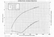
I just checked the GE datasheet for 6550A and it has a more typical distortion versus loading curve for P-P class AB.
Some ramping to the left side still, due to gm variation with current. But since the 2nd Harmonic (seen in the SE curve) is missing (cancelled out), only odd harmonic components are left in. The ramping on the right side is the usual odd harmonics from screen grid current becoming significant at high Z load.
The optimum low dist. point around 5000 Ohm might involve some odd harmonic cancellation between the variable gm mechanism and the screen current mechanism. Otherwise, I don't think the null point would be so sharp. (no reason to expect gm variation would just end at 5500 Ohms as it appears)
http://tubedata.milbert.com/sheets/135/6/6550A.pdf
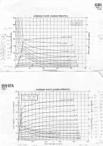
Pic 2 is a comparison of 6JB5 versus 6V6 plate curves. Both tubes have the same nominal specs on paper. But definitely not the same curve shapes. Would be interesting to see if the square knee'd 6JB5 reduces some of the odd harmonic dist. at high Z load. But no loading curves are given for either. The 6V6 curves still look like there would be a smooth gm variation for a very specific Zload line, it just has to cut through the plate curve slopes in the optimum place and maybe stay above 75V. I would guess the 6V6 has a narrower optimum Zload distortion null than the 6JB5.
.
Some ramping to the left side still, due to gm variation with current. But since the 2nd Harmonic (seen in the SE curve) is missing (cancelled out), only odd harmonic components are left in. The ramping on the right side is the usual odd harmonics from screen grid current becoming significant at high Z load.
The optimum low dist. point around 5000 Ohm might involve some odd harmonic cancellation between the variable gm mechanism and the screen current mechanism. Otherwise, I don't think the null point would be so sharp. (no reason to expect gm variation would just end at 5500 Ohms as it appears)
http://tubedata.milbert.com/sheets/135/6/6550A.pdf
Pic 2 is a comparison of 6JB5 versus 6V6 plate curves. Both tubes have the same nominal specs on paper. But definitely not the same curve shapes. Would be interesting to see if the square knee'd 6JB5 reduces some of the odd harmonic dist. at high Z load. But no loading curves are given for either. The 6V6 curves still look like there would be a smooth gm variation for a very specific Zload line, it just has to cut through the plate curve slopes in the optimum place and maybe stay above 75V. I would guess the 6V6 has a narrower optimum Zload distortion null than the 6JB5.
.
Attachments
Last edited:
Don't listen to innernet chatter from guys like Andrew, JM, orTubeLab. And especially that kook PRR.
No, listen to your speakers instead, especially the bass. When an SE tube amp without feedback has a damping factor between 1 and 3, some speakers will react to a slight improvement by connecting them to a lower impedance tap than their "rated impedance." Others could care less. This is quite noticeable on my Yamaha NS-10's.
There is an autotransformer intended for OTL amps called the Zero. It allows you to vary load impedance on an amp by choosing a different tap. They're not cheap, but it should be possible to wind your own.
As I already mentioned above,
4 Pack Rotary Speaker Volume Control Wall Mount Home Ceiling Speaker Dial (New)
4 Pack Rotary Speaker Volume Control Wall Mount Home Ceiling Speaker Dial (New)
Perhaps one matter not to be ignored in all this.
Referring to the left-most graph in post #22 (Smoking-amp), one finds a minimum in total distortion at about 5K load. But one must remember that the graph is for distortion percentage. This is normally taken just before overload. Thus, bringing the rapidly falling graph for maximum output into the mix as the fraction denominator, the actual signal distortion 'produced' does fall as well, just not so fast as the maximum power output.
Measured distortion at a lower constant output level, somewhat below the maximum available level, will show a different tendency, which will be falling all the time, and this is where listening normally takes place.
Just to make matters nice and easy!
"Thus, bringing the rapidly falling graph for maximum output into the mix as the fraction denominator, the actual signal distortion 'produced' does fall as well, just not so fast as the maximum power output."
Good point Johan. We do need a full 3-D graph to really see what goes on there.
And higher odd harmonics would have a faster decay with lower demanded power output typically. And then, at some level, there is the class A region in class AB as well. Presumably these tube distortion graphs are for the output stage only and with some optimal class AB idle current. When the front end and N Fdbk are included, hopefully all this distortion falls below the threshold of hearing. I guess for those who really want to check, there are the FFT programs with a sound card to find out what the amp actually does.
The reason this all caught my attention is that I've been trying to come up with a heuristic formula for selecting the optimum primary load impedance for a set of tubes in class AB. Something like this works well (but may be improvable):
Zp-p = k x Pdiss x (B+ - 60V) x (B+ - 60V) / (Watts_out x Idc)
Pdiss is tube max Watt rating (size of plate)
Idc is max DC current rating (size of cathode)
Watts_out compensates for running tubes below max power (or current) capability, could be done differently (like Pdiss used, or max current used)
B+ is operating power supply voltage
k is a constant selected to fit known tube data cases the best
This formula can be fitted to most of the common tubes that give class AB operation data (including multiple data sets). Then one can plug in an unknown tube (like some TV Sweep) to select an OT. A work in progress.
.
Last edited:
Using 7 secondary wires now, I can get 4, 6, 8, 12 and 16 Ohm output with efficient secondary winding use:
Two 4 Ohm windings, each with a center tap, and one of those with a 1/4 tap.
Using 8 secondary wires, can get 4, 5, 6, 7, 8, 10, 12, 14, and 16 Ohm outputs efficiently utilized:
Use two 4 Ohm windings, each with a center tap, and one of those with a 1/4 tap and a 1/8 tap.
I really don't understand how this should work. Using center-tapped 4 ohms windings, we should additionally expect impedances of odd ohms numbers. Tapping at 1/4 would lead to impedance numbers that end with 0.25, tapping at 1/8 to 0.0625 endings.
Best regards!
Neither does he.
The impedance varies with the square of the turns ratio.
If he has two 4ohms windings then when he series connects them he has doubled the number of turns. Now sqaure that 2:1 turns ratio and he should get a 4:1 impedance ratio, i.e. two 4ohms windings gives a 16ohms total winding.
If we start with a notional 10Turn for a 1ohms winding,
then for a 2ohms he would require Sqrt(2) * 10T = ~14T
For 3ohms he would require Sqrt(3) * 10T = ~17T
For 4ohms he would require Sqrt(4) * 10T = 20T
For 8ohms he would require Sqrt(8) * 10T = ~28T
etc.
The scheme is working. I just rounded the Ohms off.
Each 4 Ohm winding has a 1/4 tap, 1/2 tap and 3/4 tap.
Paralleling the 4 Ohm windings gives 4 Ohms out.
Now shift one winding off by 1/4 tap to get 1.25 x turns squared or 6.25 Ohms.
Shift by 1/2 tap to get 1.5 x turns squared or 9 Ohms
Shift by 3/4 tap to get 1.75 x turns squared or 12.25 Ohms
Shift by 1 (series connect) for 2 x turns squared or 16 Ohms
The overlapped and shifted windings get connected in two places, so the overlap part is paralleled.
So 4, 6.25, 9, 12.25, 16 Ohm outputs from 8 secondary wires (shift windings opposite way to get the 3/4 case, saves 2 wires)
I just rounded to integers. 9 was close enough to the traditional 8 Ohm.
(or could make the 4 Ohm windings into 8/9 x 4 = 3.5555 Ohms to get exactly 8 Ohm for the 9 Ohm tapping, then getting: 3.5555, 5.5555, 8, 10.88888, 14.2222)
With 1/8 taps, then we get: 4, 5.0625, 6.25, 7.5625, 9, 10.5625, 12.25, 14.0625, 16 Ohms
for 12 secondary wires. (use same trick to shift opposite way for 5/8, 3/4 and 7/8 taps to save 6 wires)
.
Last edited:
This morning and in another thread (Yet More Discussion on Winding Output Transformers) I've shown a way to get today's most usual impedances without any tapping.
Best regards!
Best regards!
Right. It's just a trade-off to avoid taps and unused winding sectionsUmmm, 4 x 1 Ohm windings gives 8 wires by my count.
.Do we really need these impedance values? For which speakers, and how often?Same thing. I don't see 6 or 12 Ohms though. Could get those by a center tap on one of the 1 Ohm windings.
Best regards!
Well, the original poster wanted a variable output transformer.
The Variac approach didn't seem too practical.
Could be interesting to adjust a speaker to see where it sounds best.
The OT winders aren't going to like 8 or 12 secondary wires though.
I think this may be further optimize-able still (fewer wires), by just putting the fine adjust taps on one end of the secondary. Fine adjusting by shortening the fine adjust end. Not much wasted winding then.
(coarse adjusts still done by conventional paralleling means, either the shifting or actual paralleling we mentioned so far.)
Last edited:
On that post #22 graph of distortion (left pic) for the 6550A tube that Johan commented on. I just noticed that the input signal is kept the same for all loading impedances. So no wonder the power output drops like a brick at lower Zload!
I was assuming the drive signal would be increased for lower Zload to keep power up some. Only increased drive signal would cause increased non-linear gm distortion, which I had been commenting on. So Johan's comment about the denominator ruling things is 100% correct in explaining the ramping distortion on the left side of that (rather mis-leading) graph.
I think someone connecting a speaker to a too low Z tapping would increase the volume control to do a sound comparison with the correct tapping. Which would cause increased non-linear gm distortion (more of the gm curve being used).
I guess the tube data graphs don't show case that however.
> I just noticed that the input signal is kept the same for all loading impedances.
That is true for nearly all the old data.
Which is why I commented that it needs interpretation.
In Real Life, we would adjust the drive as appropriate. As has been said, the THD will not rise as fast, but the Watts for a consistent THD would fall off more.
I still do not think it is "critical". 2:1 taps will get as close as you can need, if you have more-than-enough Power. If you are under-powered, you will always be on the edge of unhappiness.
Yeah, clearly, a little extra amplifier reserve power is the best way to solve the matching issue.
But,
I just happened to recall the old surplus 400 Hz Variacs that used to be available. These tended to have heavy wire windings, and probably a mixed copper/carbon brush. Using say a 15 Amp 120V or 240V one, across two OT taps, might give decent variable Z results, and possibly still working at HF well (thinner core lamination?). If you can find one still. They used to be cheap.
Last edited:
> possibly still working at HF well (thinner core lamination?).
Lam thickness must be small for 400CPS *power* work. Eddy current loss makes heat, power transformers run full voltage all day long.
In audio, the losses are less because we work at very low average flux, and because frankly we audio-heads can tolerate losses that are uneconomic in power work. (Incandescent lamps were more voltage-fussy than ears are.)
Auto-transformer at 1:1 will be very wide-band.
Turn the tap to 50%. Half the primary is same-as secondary. Other half of primary is "distant" from secondary. It is throwing out leakage inductance which misses the secondary by inches. Treble loss will be large, at least for the standard Variac construction.
- Status
- This old topic is closed. If you want to reopen this topic, contact a moderator using the "Report Post" button.
- Home
- Amplifiers
- Tubes / Valves
- Newbie basics - variable output transformer