tmhajw said:As I understand it, lifting the earth in your monoblocs will encourage the signal grounds to flow back to your preamp, as they should.
The simplest way to do this is to locate your earth wire on the immediate inside end of your power supply socket, cut it & insert a 47 ohm resistor. This should incidentally present little problem for chassis earthing should any catastrophe occur & it ever go live.
Try it and see. You can easily reverse it....
Thomas
I've done some more reading on the subject of ground loop issues and the possibility of "lifting the ground"...as I understand it, this process would help eliminate grounding problems due to other equipment being used in association with the amp and therefore the noise that might result. Since the amp is completely isolated, as I mentioned above, other than its power source and its connection to the speaker and still creates the noise this seems like a dead end. If I'm wrong, please explain why.
While considering the issue of lifting the ground, I had taken another look at the grounding of the amp in question. I noticed for the first time while examining the chassis ground point at the power cable socket that the paint surface was not scrapped away where the ground strap was bolted down. While shifting the wire gently it snapped off in my fingers...gotta love that built in China quality! At any rate, I disassembled it all, cleaned the paint off the grounding point and repaired everything properly. Then I checked for continuity through the chassis from the socket to all the various grounding points in the amp. A re-test of the amp showed no difference, it still makes the same noise.
I also decided to short the inputs after trying to read more about it. I'm not really sure what it rules out in this situation. I took an old cheap RCA connector, cut the leads and shorted them out, tested for continuity between the center contact and outer ground, plugged it into the amp and powered it up. No difference, the amp still makes the same noise.
In considering the situation further, and trying to absorb more information, I've started to understand that there is a difference between "hum" as described in electronic circuits and hum as I would describe it from a layman's perspective. I am trying to determine now if what I am really hearing is what would be considered "ripple" which would be a 120Hz noise (as Ty_Bower previously mentioned). My judgment is completely subjective on this matter, and lacks any real experience. After listening to the amp a few more times today, I would have to say that if this noise was "hum" (60Hz) that I would imagine its frequency to be very deep sounding, this noise does not have that quality to my ears. I would be more inclined to say it sounds more like "ripple" or a 120Hz noise. That being the case, it would seem that I need help trying to troubleshoot the power supply and/or internal wiring according to what I have read in some of the more simplistic troubleshooting flow charts I have seen.
As a matter of course I would like to check the capacitors to see if there are any obvious signs of a bad capacitor. Can this be done with the capacitors installed in the amps circuit board? or do they need to be removed? I have read conflicting info about this...if someone can point me in the right direction I would appreciate it. I assume I am testing for resistance. All I have is a standard Craftsman digital multimeter on hand. Thanks.
Not sure if this was mentioned yet or not:
C4 and C5 look to have quite long leads,and it appears that C4 is right next to the AC power wiring?
I would suggest trimming the leads a bit,and getting them a bit closer to the board,and away from the AC wiring. It could be picking up hum and injecting it right into a tube's grid.
C4 and C5 look to have quite long leads,and it appears that C4 is right next to the AC power wiring?
I would suggest trimming the leads a bit,and getting them a bit closer to the board,and away from the AC wiring. It could be picking up hum and injecting it right into a tube's grid.
DigitalJunkie said:Not sure if this was mentioned yet or not:
C4 and C5 look to have quite long leads,and it appears that C4 is right next to the AC power wiring?
I would suggest trimming the leads a bit,and getting them a bit closer to the board,and away from the AC wiring. It could be picking up hum and injecting it right into a tube's grid.
Yes...this was mentioned a few times. Whether or not it was an issue, I wasn't sure. I thought the extended leads might also add more resistance to the circuit (more on this later).
At any rate, I was checking the resistance of the capacitors in the amp today (I had read that they should pretty much read infinite and I should see the resistance continue to increase as the caps charged if I had my multimeter connected to them in the correct polarity and they were not leaking) this only seemed to work partly in theory with the caps still mounted on the circuit board, as the longer I tested them the slower the seemed to charge, and they never seemed to charge as fast as some of the new caps I tested that had not been installed.
As I sat scratching my head and trying to think of what to do next, I decided that I might give shortening the leads on the C4 and C5 caps a shot. While I was at it, I used Ty's response to my questions about these earlier as a guide to reinstall them with the correct polarity.
Ahhh...the putrid stench of fried resistor. Don't ask me what happened. I shortened the leads and set the caps back in place having to only reverse the polarity of one of them (C5).
The first time I powered the amp up I didn't know what to make of it. The sound through the speaker was sort of like an oscillating distortion of some sort. Almost sounded like a flag waving in the wind. I shut it down quick and took a look at the board and caps to see if anything obvious looked wrong.
I decided to put C5 back to how it had been installed, rechecked everything visually and tried firing the amp again.
Same thing happened. I listened for a second too long, the second time. R14 on the board is fried. I'm not sure what happened. I thought that maybe some solder I lost track of might have shorted something out, I can't find anything obvious. Right now I'm on my way to Radioshack to see if I can come up with a 390 1/2 watt replacement.
This just gets better and better. Am I even learning anything here? or am I just banging my head against the wall and screwing up any chance of getting this thing fixed? Ugh!
chromenuts said:The sound through the speaker was sort of like an oscillating distortion of some sort. Almost sounded like a flag waving in the wind.
I think the term for what you describe is commonly known as "motorboating".
I can't imagine that anything you would have done with C4 and C5 would have cause this. Something else must be going on...
Ty_Bower said:
I can't imagine that anything you would have done with C4 and C5 would have cause this. Something else must be going on...
First of all, I must state that I am not an expert and I am just learning...
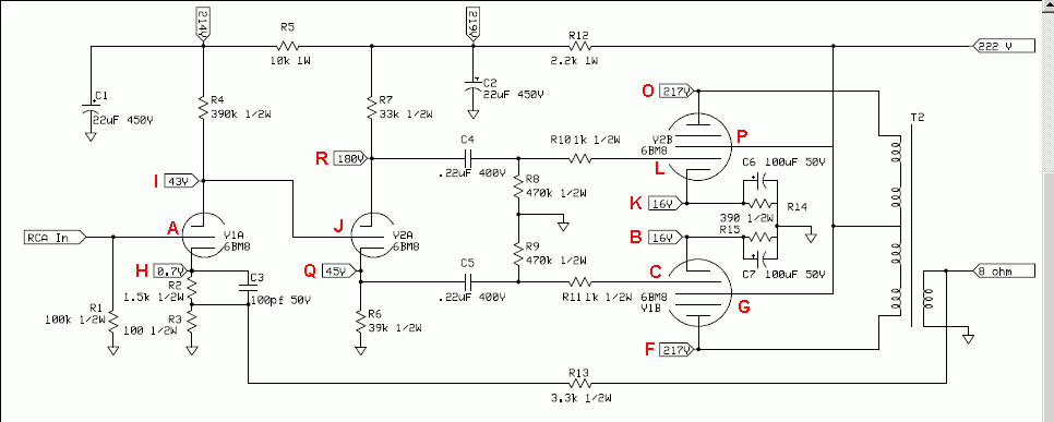
To my eyes, shorting out C4 and C5 has caused problems. C4 and C5 are coupling capacitors that keep the DC voltage out of the signal that is sent to the grid of the pentode section of the valve. Shorting these out means that you are biasing the grid of V2B with +180 volts and the grid of V1B with 45 volts. Looking at the plate curves for the pentode section of the 6BM8, with those kinds of bias voltages, you are way off the curves at 200mA+. 200mA across your bias setting resistors R14 and R15 is going absolutely fry them (as you found out).
Also, using a little Ohm's law, you will see that there is an error in the schematic for the rating of R14 and R15. with about 40mA flowing through the valve, these resistors will be dissipating around .6 to .7 Watts, a 1/2 watt resistor is not going to be good enough here. I would use a 2 watt or better.
Guess I should put my glasses on ")
Maybe whoever sold them had problems after the mods they made and tried selling them to make them someone else's problem...
FWIW, I am in my study now, and my amp in here is a copy of this cct. I do get some humm at the speakers, but not much and not audible from 30cm away. I did, however, add more power supply filtering. It was a cheap build to try my hand at a point to point design, so I did not use a choke. I ended up with a CRCRCRC filter, as i had two JJ dual can caps (40+40 and a 100+100).
Chris
Ty_Bower said:He shortened the leads - as in "make them not as long." He did not short the leads, or make it a short circuit. At least, I hope he didn't. That would be a bad thing.
No I did not create a short circuit in place of C4 and C5.
chrish said:Guess I should put my glasses on
Maybe whoever sold them had problems after the mods they made and tried selling them to make them someone else's problem...
FWIW, I am in my study now, and my amp in here is a copy of this cct. I do get some humm at the speakers, but not much and not audible from 30cm away. I did, however, add more power supply filtering. It was a cheap build to try my hand at a point to point design, so I did not use a choke. I ended up with a CRCRCRC filter, as i had two JJ dual can caps (40+40 and a 100+100).
Chris
You may be right about the reason for sale...I guess the reason doesn't really matter. That's the risk you take with used equipment. I've had my share of issues with used pieces...nothing like this before though. The thing about the "hum" is that the
other mono-block sounds fine...as you describe your amp, very little noise unless you listen very closely to it, and there is no obvious difference (except the cap I changed out in the noisy one not being up to spec). The bad amp is has a very pronounced and distracting hum which I have speculated (due to inexperience) is more likely considered ripple since it sounds more like a 120Hz noise than a 60Hz noise to me.
Ty_Bower said:I'm still extremely suspicious of the power supply caps (C8 and C9). The original hum, now the motorboat symptoms all seem to point towards it. Were C8 and/or C9 ever replaced?
I'm now back to square one. I tested R14 before moving forward, and remarkably it still showed the correct resistance. I did manage to get replacements, but decided to leave it for now. I cleaned down the board with some alcohol and a toothbrush so I could see everything more clearly. As I was working on it, I noticed a small blob of solder seemed to wash out from under one of the tube sockets. It was in close proximity to where I had been working on one of the caps and must have migrated off the backside of the iron without my noticing it.
P.S. C9 was the cap that was replaced because it was not up to spec according to the manufacturers schematic.
So now I have the same wonderful humming amp as before...except with shortened leads on the filtering caps. Yippie!
Once again, I am not an expert, so take my advice for what it is worth...
If there is evidence of any damage to components, replace them, even if they test OK. If the resistors were smoking, they were passing too much current. Try to find out why before re-applying power. R14 and R15 require 2Watt resistors. They are only a few cents each, so use the right rating or you WILL end up with more problems in the future.
1. You have two monoblocks, one works one does not.
2. You have a multimeter.
3. You have a schematic.
4. You have the help of the members of this forum.
5. You should be able to get a free program to turn your PC in to a simple tone generator.
I would suggest printing out two copies of the schematic and mark them clearly "working amp" "humming amp" or similar.
I would then start taking readings with the multimeter, both AC and DC in a systematic manner. Ty suspects power supply, so it might be as good a place as any to start.
Check the diodes of the power supply with the diode test of the multimeter, should be open cct when reverse biased and show correct forward drop when forward biased.
Check the voltage (AC and DC) at C9, then C8, then C2, then C1. Hopefully this will show any problems with power supply and filter caps. If the non-working amp has greater AC, then there is a filtering problem.
Measure at all of the points on the schematic that have a DC voltage reference.
Measure the DC voltage at the junction of R8 and C4 and also the junction of R9 and C5 to see if you have leaking coupling caps (there should be 0 DC voltage at these points).
When taking these measurements with the power on BE EXTREMELY CAREFUL! Clip the negative probe of the multimeter to GND and use the positive probe to take readings. Put your other hand behind you back, in you pocket etc. Do not use it to steady the amp, hold the chassis etc!
Report back with results...
Chris
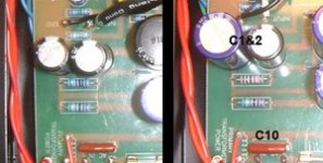
chromenuts said:I also noticed some differences in the size and color coding of some resistors from one amp to the other at the R5, R14 and R15 positions. Since I can't decipher the color coding as of yet, I don't know what to think.
Take a closer look at R5, and tell us what you find. Use your ohmmeter and measure it on both amps.
Attachments
Originally posted by chrish
If there is evidence of any damage to components, replace them, even if they test OK. If the resistors were smoking, they were passing too much current. Try to find out why before re-applying power. R14 and R15 require 2Watt resistors.
Yes...I agree, I was simply commenting on the fact that I was amazed that the resistor actually still tested good after the smoke show. I was more interested at that point in trying to figure out why things changed so dramatically so quickly than putting in a replacement. Interestingly enough, I think the ASL manufacturers also realized that those resistors needed to be 2 watt. More info on this below.
1. You have two monoblocks, one works one does not.
2. You have a multimeter.
3. You have a schematic.
4. You have the help of the members of this forum.
I would suggest printing out two copies of the schematic and mark them clearly "working amp" "humming amp" or similar.
I appreciate the input. I kind of felt like I was simply poking around in the dark. My electronics aptitude is limited. I feel at this point almost like someone who has learned some expressions in a foreign language who is trying to speak in it conversationally.
I decided to start with something I understand. I have made a spreadsheet that includes all of the specifications for the resistors in the amp circuit as defined in the schematic and the actual measurements that I was able to make on both amps. The information and my observations are below.
I would then start taking readings with the multimeter, both AC and DC in a systematic manner. Ty suspects power supply, so it might be as good a place as any to start.
This is not something I can say I feel confident or competant about. I don't have enough of an understanding of electrical schematics to differentiate exactly where AC or DC should be measured. I understand the idea, and assume a transformer would be responsible for converting the current.
Check the diodes of the power supply with the diode test of the multimeter, should be open cct when reverse biased and show correct forward drop when forward biased.
cct? reverse biased? forward drop? etc....sorry, your talking above my head. I will read the manual for the tester I have and see if it says anything about testing diodes. If not I'll do a search on the subject.
Check the voltage (AC and DC) at C9, then C8, then C2, then C1. Hopefully this will show any problems with power supply and filter caps. If the non-working amp has greater AC, then there is a filtering problem.
This is confusing to me. I don't understand how this test would be performed (I want to avoid damaging me and the Amp), and I am confused by the idea of there being measurements for both AC and DC at the same point in the circuit.
Measure at all of the points on the schematic that have a DC voltage reference.
How do I determine which are DC? Other than my preconception that AC voltages should be higher? Is it based on a certain point in the circuit diagram beyond where a transformer is located?
Measure the DC voltage at the junction of R8 and C4 and also the junction of R9 and C5 to see if you have leaking coupling caps (there should be 0 DC voltage at these points).
I'll try to get this info later.
My accomplishment for the day. As stated above, a spreadsheet with resistor data.
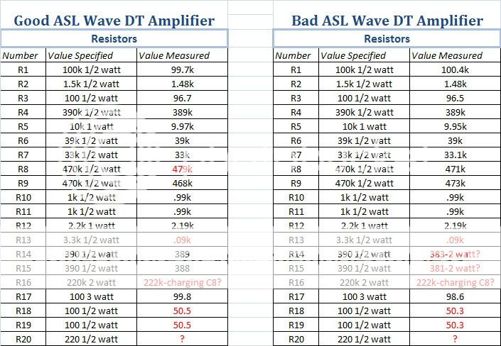
Comments:
Even though its less than a 2% difference, why is the resistance on R8 that much higher? Quality control?
What is up with R13 in both amps? It calls for a 3.3k 1/2 watt, but measures only .09k! I rechecked my measurement about six times. The measurement is consistent from one amp to the other.
R14 and R15. This is what I was commenting on above. After testing so many resistors and noting a pattern in both resistor size and their rating in watts, I realized that these two resistors (one of which was toasted last night) appear to actually be 2 watt rated in the humming amp. You can reference my pics of them inside the amp early in my post and see they are considerably larger in size than most others, and pretty much the same size as the other resistors that are supposed to be rated at 2 watts. I also commented on them being different from what was installed in the amp that is functioning well (which evidently only has 1/2 watt pieces installed in the same location). I suppose someone realized they needed to be rated higher at some point? I guess that leaves me to change out the pair in the good amp at some point? (right now, if it ain't broke don't fix it).
R16. This was strange. While taking the measurement, the resistance increased very gradually (as it did when I was measuring the caps in the amp). It appeared to max out around 222k, I left the probes in place for a few minutes afterward. I guess this has something to do with its orientation to the C8 cap in the circuit?
R18 and R19. Measured the same in both amps. Only around 50 ohms as opposed to 100 that it calls for in the schematic. I suppose this like some of the other discrepancies could be written off to modifications being made during the manifacture process that were never changed in the schematic?
P.S. R20, although noted in the schematic, was nowhere to be found on the board. After studying the schematic more I thought that it appeared the resistor was associated with the only LED that is present in the amp. It is used to indicate power on the front panel. This LED has two bulky shrink wrapped leads that appear to me as if they could conceal a resistor inline? I wasn't able to test the lines with any certainty and didn't think i should mess with what looked like delicate leads on the LED.
If there is evidence of any damage to components, replace them, even if they test OK. If the resistors were smoking, they were passing too much current. Try to find out why before re-applying power. R14 and R15 require 2Watt resistors.
Yes...I agree, I was simply commenting on the fact that I was amazed that the resistor actually still tested good after the smoke show. I was more interested at that point in trying to figure out why things changed so dramatically so quickly than putting in a replacement. Interestingly enough, I think the ASL manufacturers also realized that those resistors needed to be 2 watt. More info on this below.
1. You have two monoblocks, one works one does not.
2. You have a multimeter.
3. You have a schematic.
4. You have the help of the members of this forum.
I would suggest printing out two copies of the schematic and mark them clearly "working amp" "humming amp" or similar.
I appreciate the input. I kind of felt like I was simply poking around in the dark. My electronics aptitude is limited. I feel at this point almost like someone who has learned some expressions in a foreign language who is trying to speak in it conversationally.
I decided to start with something I understand. I have made a spreadsheet that includes all of the specifications for the resistors in the amp circuit as defined in the schematic and the actual measurements that I was able to make on both amps. The information and my observations are below.
I would then start taking readings with the multimeter, both AC and DC in a systematic manner. Ty suspects power supply, so it might be as good a place as any to start.
This is not something I can say I feel confident or competant about. I don't have enough of an understanding of electrical schematics to differentiate exactly where AC or DC should be measured. I understand the idea, and assume a transformer would be responsible for converting the current.
Check the diodes of the power supply with the diode test of the multimeter, should be open cct when reverse biased and show correct forward drop when forward biased.
cct? reverse biased? forward drop? etc....sorry, your talking above my head. I will read the manual for the tester I have and see if it says anything about testing diodes. If not I'll do a search on the subject.
Check the voltage (AC and DC) at C9, then C8, then C2, then C1. Hopefully this will show any problems with power supply and filter caps. If the non-working amp has greater AC, then there is a filtering problem.
This is confusing to me. I don't understand how this test would be performed (I want to avoid damaging me and the Amp), and I am confused by the idea of there being measurements for both AC and DC at the same point in the circuit.
Measure at all of the points on the schematic that have a DC voltage reference.
How do I determine which are DC? Other than my preconception that AC voltages should be higher? Is it based on a certain point in the circuit diagram beyond where a transformer is located?
Measure the DC voltage at the junction of R8 and C4 and also the junction of R9 and C5 to see if you have leaking coupling caps (there should be 0 DC voltage at these points).
I'll try to get this info later.
My accomplishment for the day. As stated above, a spreadsheet with resistor data.
Comments:
Even though its less than a 2% difference, why is the resistance on R8 that much higher? Quality control?
What is up with R13 in both amps? It calls for a 3.3k 1/2 watt, but measures only .09k! I rechecked my measurement about six times. The measurement is consistent from one amp to the other.
R14 and R15. This is what I was commenting on above. After testing so many resistors and noting a pattern in both resistor size and their rating in watts, I realized that these two resistors (one of which was toasted last night) appear to actually be 2 watt rated in the humming amp. You can reference my pics of them inside the amp early in my post and see they are considerably larger in size than most others, and pretty much the same size as the other resistors that are supposed to be rated at 2 watts. I also commented on them being different from what was installed in the amp that is functioning well (which evidently only has 1/2 watt pieces installed in the same location). I suppose someone realized they needed to be rated higher at some point? I guess that leaves me to change out the pair in the good amp at some point? (right now, if it ain't broke don't fix it).
R16. This was strange. While taking the measurement, the resistance increased very gradually (as it did when I was measuring the caps in the amp). It appeared to max out around 222k, I left the probes in place for a few minutes afterward. I guess this has something to do with its orientation to the C8 cap in the circuit?
R18 and R19. Measured the same in both amps. Only around 50 ohms as opposed to 100 that it calls for in the schematic. I suppose this like some of the other discrepancies could be written off to modifications being made during the manifacture process that were never changed in the schematic?
P.S. R20, although noted in the schematic, was nowhere to be found on the board. After studying the schematic more I thought that it appeared the resistor was associated with the only LED that is present in the amp. It is used to indicate power on the front panel. This LED has two bulky shrink wrapped leads that appear to me as if they could conceal a resistor inline? I wasn't able to test the lines with any certainty and didn't think i should mess with what looked like delicate leads on the LED.
chromenuts said:I decided to start with something I understand. I have made a spreadsheet that includes all of the specifications for the resistors in the amp circuit as defined in the schematic and the actual measurements that I was able to make on both amps.
Comments:
Even though its less than a 2% difference, why is the resistance on R8 that much higher?
What is up with R13 in both amps? It calls for a 3.3k 1/2 watt, but measures only .09k!
R14 and R15... appear to actually be 2 watt rated... I guess that leaves me to change out the pair in the good amp at some point? (right now, if it ain't broke don't fix it).
R16. This was strange. While taking the measurement, the resistance increased very gradually...
R18 and R19. Measured the same in both amps. Only around 50 ohms as opposed to 100 that it calls for in the schematic.
P.S. R20, although noted in the schematic, was nowhere to be found on the board. After studying the schematic more I thought that it appeared the resistor was associated with the only LED that is present in the amp.
R8 - I wouldn't worry about a 2% difference. It's within tolerance. That's the "grid leak" resistor. It keeps the grid at ground potential so the tube remains correctly biased.
R13 makes me think a bit. That's the feedback resistor. It takes a sample of the signal from the output, then feeds it back into the input stage. The feedback signal comes into the circuit 180 degrees out of phase with the source signal. Non-linearities, noise, and other junk that mistakenly got generated in the amp is supposed to get canceled out. Smaller resistor = more feedback. You'd have to fully understand the design of this amp to know whether the (much) smaller value used here is OK. I'd be tempted to try to restore it to the original schematic value. This will probably not fix your humming problem - it might even make it worse.
R14/R15 are the output cathode resistors. Two watts makes sense here. I'll agree with your "ain't broke" philosophy for the time being.
Attempting to measure R16 will charge up the supply caps. It's in parallel with them. Attempting to check the supply caps with your ohmmeter for DC leakage will result in a measurement of R16. One of the (many) reasons why checking caps with a ohmmeter doesn't always give valid results.
R18 and R19 create a phantom center tap on the filament winding. Their exact value isn't all that critical, but R18 should be the same as R19. Grounding the junction between them keeps the winding's potential at ground. Keeping a handle on the voltage potential between the tube's heater (filament) and it's cathode is important to the tube's health. You'll see references to maximum H-K potential in the tube datasheets. It's nice if the filament can be kept at the same voltage as the cathode, but that's not always practical.
You are measuring all of these resistors attached to the cct (circuit). The schematic shows that the feedback resistor is attached to ground at each end (through the output transformer). You would therefore expect a very low reading for this resistor when it is in the cct.
I have tried to give you a systematic approach to solving this by giving us data that is easy to take. You can chase your tail, or use your head. A systematic approach will help narrow down where the problem is originating.
Step 1 - After changing the cathode bias resistors PUT YOUR SOLDERING IRON AWAY until you know what to change.
Step 2 - TAKE THE READINGS ASKED FOR. As I stated above, to take a reading you attach the ground lead of the multimeter to a ground point on the printed circuit board. A lead with an alligator clip works best here. Leave that lead attached. Use the positive lead of the multimeter (a pointy type probe is best here) and touch the circuit board traces at the appropriate places and take the readings. The B+ voltages and all of the voltages on the schematic are DC voltages. Use the DC setting of your meter to take these readings. Measure the AC voltages at the places I mentioned too. Use the AC setting of your meter to do this. By measuring the AC voltage we can see if there is still a large amount of AC coming out of the power supply. This may cause humm and may be your problem. Being able to compare with a working amp will help show any problems.
We can't help you if you cannot give us useful information.
Re reading my post above, it might come across as a bit harsh, sorry, not my intention.
The feedback resistor, if I did not make myself clear, do not replace it, it is probably fine. The reading you got was what I would expect, due to its placement in the circuit.
As for the other stuff, my point is that if you randomly change parts without reason, you will end up frustrated, learn nothing, may not solve the problem and may end up damaging things further. A systematic approach is best, and will hopefully help you (and us) learn along the way.
chrish said:The feedback resistor, if I did not make myself clear, do not replace it, it is probably fine. The reading you got was what I would expect, due to its placement in the circuit.
Of course. Thanks for spotting my error. Guess I'm stupid.
That's why I don't work on my amps at midnight. I probably shouldn't be posting misinformation at midnight, either.R13 is effectively in parallel with R3 when measured in circuit. The DC resistance of the output transformer is small enough to be ignored. 1/(1/3.3K + 1/100) = 0.09K, exactly as measured.
chrish said:Re reading my post above, it might come across as a bit harsh, sorry, not my intention.
The feedback resistor, if I did not make myself clear, do not replace it, it is probably fine. The reading you got was what I would expect, due to its placement in the circuit.
As for the other stuff, my point is that if you randomly change parts without reason, you will end up frustrated, learn nothing, may not solve the problem and may end up damaging things further. A systematic approach is best, and will hopefully help you (and us) learn along the way.
No problem. I agree that what was needed was organization and a systematic approach.
It is hard to be in a situation like this after such a long time where I feel like my understanding is at absolute ground zero. It requires humility. I apologize if I come across as being dense.
I am trying to find more material that will give me a better understanding of interpreting schematics and circuits, and hopefully will help me identify how the design relates to the actual PCB.
I will try to start taking measurements as I am able to identify the proper locations on the board as compared to the schematic. It is going to be a horse of a job with the functioning amp. It appears that whoever assembled it left fairly short leads from the transformers to the board which prevent it from swinging out of the chassis very far. It limits access quite a bit.
As for today, well nothing got done except me trying to spend some time with my wife on Valentines Day.
Spend the time with your family! Much more important than hobbies...
The best way to relate the board to the schematic is if you kind of think of the schematic like one of those idealised public transport system maps (like the famous London underground railway map). The schematic will show what part is connected to what, but not necessarily to scale. You should be able to trace it out. What can also be helpful is if the circuit board has the components labelled and if you have a schematic with the same identifiers. In this case you do, as you have already been able to identify the placement of all the resistors and capacitors. You are 95% of the way there. For example, to identify where to take the reading for the "219V" point on the schematic, look for the circuit board trace that joins R12 to the positive (+) side of C2 and to R7 and R5. You can touch your multimeter probe anywhere along this trace for that reading. Once you have identified that point, look to the other side of R5 to take the "214V" reading. R5 connects to R4, so on the other side of R4 take the "43V" reading etc...
I am away with work for the next three or four days, so may not be able to contribute till back, but hopefully someone can lend a hand once you take the readings.
Good luck,
Chris
chromenuts said:I am trying to find more material that will give me a better understanding of interpreting schematics and circuits, and hopefully will help me identify how the design relates to the actual PCB.
I will try to start taking measurements as I am able to identify the proper locations on the board as compared to the schematic. It is going to be a horse of a job with the functioning amp. It appears that whoever assembled it left fairly short leads from the transformers to the board which prevent it from swinging out of the chassis very far. It limits access quite a bit.
One of my favorite sites for learning about vacuum tubes amplifiers is this one: http://www.freewebs.com/valvewizard/. It covers many of the basic principles in a way that is relatively easy to follow.
As far as measuring is concerned, I would not try to take voltage measurements with the circuit board hanging out of the chassis. If you leave it mounted, most (if not all) of the interesting test points will still be accessible from the underside of the board. You can get all of the points in the power supply section by touching the tip of the probe to one end of a resistor, and simply checking the pins of the tubes (where the socket is soldered into the board) will tell you what you need to know about the amplifier portion of the circuit.
This page shows you which pin is what on the 6BM8: http://tdsl.duncanamps.com/show.php?des=6bm8
As a general rule of thumb, tubes work by applying a high voltage (100 volts or more) to the plate. The cathode is kept at a voltage lower than the plate, or sometimes even at ground potential. The grid is kept even lower than the cathode. Knowing this might also help you identify which pin is which.
Somebody ought to check my work, but I think I have this correct... Maybe this will help you line up a few of the points on the schematic with places on the actual circuit. As Chris suggests, you'll want to clip the black lead of your meter to any ground point on the amp. Power it up and cautiously measure the DC voltage at each test point. Record them as you go along. They should match what you see on the schematic.
Then go back again with the meter set to read volts AC and measure each point again. It's a shame most common meters won't read anything less than 0.1 VAC. You really want to be able to measure millivolts AC, but for that you'd probably need an oscilloscope.
Keep a load on the outputs (speakers or dummy resistor) and the RCA input jacks shorted during the test. Use one hand to work the meter probe and keep the other hand away from the amp.


- Status
- This old topic is closed. If you want to reopen this topic, contact a moderator using the "Report Post" button.
- Home
- Amplifiers
- Tubes / Valves
- Newbie and ASL Wave 8 problems