Scott,
Yes, a few years back SpeakerBuilder had an article where somebody had compared lining to stuffing a TL. What I concluded from reading the article, and thinking about the plotted data, was that lining can also be very effective in controlling the quarter wave modes. The wavefront profile will be flat across the cross-section so the lining will help attenuate the sound wave, there will be air velocity traveling in the lining. The air velocity cannot vary across the cross-section, no shear stresses allowed in the air. You get a similar effect as with stuffing. What you loose is any attenuation of the transverse standing waves, the velocity will be minimum at the walls and these waves are better damped by fiber on the centerline of the TL.
By the way -do you have any thoughts or views regarding lining, rather than stuffing the cabinet? (oh boy, I've started at it now!)
Yes, a few years back SpeakerBuilder had an article where somebody had compared lining to stuffing a TL. What I concluded from reading the article, and thinking about the plotted data, was that lining can also be very effective in controlling the quarter wave modes. The wavefront profile will be flat across the cross-section so the lining will help attenuate the sound wave, there will be air velocity traveling in the lining. The air velocity cannot vary across the cross-section, no shear stresses allowed in the air. You get a similar effect as with stuffing. What you loose is any attenuation of the transverse standing waves, the velocity will be minimum at the walls and these waves are better damped by fiber on the centerline of the TL.
Greets!
FWIW, virtually everyone that followed even the minimal stuffing density I use to recommend based on MJK's work found it to be up to ~3x too much, so have quit listing a recommendation. Ditto with the few that commented on RS's Alpha TL and Quarter Wave Reflex based on Augspurger's work I posted. Typically they described it as a muffled one note bass.
Models not accurate enough or folks want more harmonic distortion than they think they do? My SWAG is it's a combination of the two, with the latter dominating.
That said, using the well proven lining of one wall, back, and top originally used by Bell Labs/W.E./Altec with damping sheeting such as low density felt, 1" acoustic or R13-R19 fiberglass insulation, has worked well whether sealed, reflex, TL, or even certain horn alignments. For sure I prefer it to the 'sound' of stuffing regardless of the materials I've tried.
GM
Hi Martin,
These are Ramon Cancel's and Todd Jenkins measures. You may recall us discussing this on the DIY list in 2003 (as part of a discussion surrounding Balaghs characterization of long fiber wool), and then in private email.
Bullock's T-line model was published in '86, and Todd and Ramon's work occurred in 93 to 95. Todd and Ramon stated the Bullock model worked very well with no stufffing. I have no reason to suspect issues with line geometry, but can't corroborate the method used. Todd had repeated the stuffing results numerous times with various materials over the course of the two years we were corresponding. Sorry that I don't have any more data than this. I believe I had sent you the measured results graphs several years back but please email me if you'd like them again.
Your similar results for wool and poly are consistent with Todd's, where he measured nearly identical attenuation profiles for them (though velocity showed differences) assuming audio grade poly from Madisound. Dacron poly was only 50% as effective, illustrating the differences in material types. If the fiber diameter and drag are similar, results would be similar.
Todd went on to work at EV 10 years ago, and I lost touch with Ramon. After a Google search I was sorry to read that Dr Bullock passed away in 2004.
Scott, the yellow compressed fiberglass is the fiber board I mentioned for my tests. If Bob is using this, then perhaps he's gunning for an attenuation tailored over frequency and location. Most of these materials have very high densities, and as my measurements show, will partially reflect if the angle isn't normal. The LDC corroborates this, with 4lb/ft3 fiberglass causing fo and f3 to increase vs 2lb/ft3. Todd found similar results.
I'm also surprised that different materials are not expected to provide differring results. I've measured wool vs poly vs glass q differences near field. Ken Kantor's on record numerous times articulating differences and preferences realized at NHT through experimentation.
Dave
Hi Dave,
Honestly, I don't rmember the discussions. I looked in my folder where I keep other people's measurements and cannot find anything from you on this topic. Not sure why.
Sure, I'll take a look.
Those are extremely high densities, if somebody is using this much fiber then they are trying to brute force a TL solution, it would be better to adjust the geometry. I have never used more then 0.5 lb/ft^3 and have recently only been using half of that amount. I don't have much faith in the LDC when it comes to TL design, it is great source for closed and vented box design information but not anything too far out of the mainstream.
I have measured polyester (cheap stuff not "audio grade") and long fober wool and achieved almost identical results. The materials had very different diameters and lengths. I have also been sent a sereis of measurments of 4 or 5 different materials and the results also are all fairly close. I don't see any magic fiber material. At this point I don't believe type of fiber is a significant variable and have stopped chasing fiber differences. I personally like cheap and readily available fibers and concentrate on better geometry solutions.
You may recall us discussing this on the DIY list in 2003 (as part of a discussion surrounding Balaghs characterization of long fiber wool), and then in private email.
Honestly, I don't rmember the discussions. I looked in my folder where I keep other people's measurements and cannot find anything from you on this topic. Not sure why.
Sorry that I don't have any more data than this. I believe I had sent you the measured results graphs several years back but please email me if you'd like them again.
Sure, I'll take a look.
The LDC corroborates this, with 4lb/ft3 fiberglass causing fo and f3 to increase vs 2lb/ft3.
Those are extremely high densities, if somebody is using this much fiber then they are trying to brute force a TL solution, it would be better to adjust the geometry. I have never used more then 0.5 lb/ft^3 and have recently only been using half of that amount. I don't have much faith in the LDC when it comes to TL design, it is great source for closed and vented box design information but not anything too far out of the mainstream.
I'm also surprised that different materials are not expected to provide differring results.
I have measured polyester (cheap stuff not "audio grade") and long fober wool and achieved almost identical results. The materials had very different diameters and lengths. I have also been sent a sereis of measurments of 4 or 5 different materials and the results also are all fairly close. I don't see any magic fiber material. At this point I don't believe type of fiber is a significant variable and have stopped chasing fiber differences. I personally like cheap and readily available fibers and concentrate on better geometry solutions.
Moving away from the stuffing debate, I mentioned I'd present a bit more on in-room matters. So...
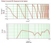
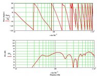
Here's a selection of responses from my Ariel MLTL thoretical design mentioned a couple of pages ago. They all assume a wooden floor, with the listener 3m away on-axis with the drivers. All I have done is move the speaker progressively from being rammed right up against a rear wall, further out into the room. Here's the first response: front baffle 15" from the rear wall. Bit of a suck-out in the mid to upper bss and lower midrange. Interesting double-dip -I imagine the second of these is floor-bounce, as it remains in basically the same place in all the graphs, but I'd be lying if I said I knew for certain -if anyone can put me right on this I'd be grateful.
Here's a selection of responses from my Ariel MLTL thoretical design mentioned a couple of pages ago. They all assume a wooden floor, with the listener 3m away on-axis with the drivers. All I have done is move the speaker progressively from being rammed right up against a rear wall, further out into the room. Here's the first response: front baffle 15" from the rear wall. Bit of a suck-out in the mid to upper bss and lower midrange. Interesting double-dip -I imagine the second of these is floor-bounce, as it remains in basically the same place in all the graphs, but I'd be lying if I said I knew for certain -if anyone can put me right on this I'd be grateful.
Attachments
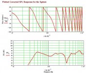
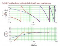
55" out. (Last one of this series this). To my eyes, this suggests that everything should be in moderation. Note that the double-dip is deeper than at 45" out, and though the bss is probably the best of the lot, it's even more ragged in detail above 500Hz.
Attachments
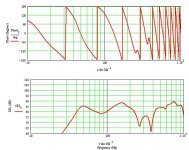
Quick divergence time. I remember hearing comments elsewhere that the F200a doesn't work in an MLTL. Well, assuming the measurements on the Fostex site are correct... it does. Bit of a pain trying to it upon some decent dimensions, but this should do OK. I extrapolated a few of the measurements not put up in the listed parameters, but I tried variations both ways and the basic response didn't alter much at all.
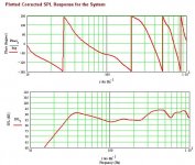
42" line length. 10 1/2" wide, 12" deep (internal.) Driver 12" down from So. Port 4" up from Sm, 4" diameter, 5" length. 0.35lbs ft^3 of stuffing.
42" line length. 10 1/2" wide, 12" deep (internal.) Driver 12" down from So. Port 4" up from Sm, 4" diameter, 5" length. 0.35lbs ft^3 of stuffing.
Attachments
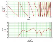
Predicted in-room nearfield response assuming it's a cabinet depth away from the rear wall and the floor is carpeted. Not too bad. Pity about the dip in the mid-bass -I think that can be mitigated against by positioning as suggested int he Ariel MLTL plots above. Overall though, I like. Should be a good one this, assuming the published specs are accurate, though I haven't yet heard the F200a driver unfortunately. Anyone out there who owns a pair and has some meaurements they've taken?
I love the sheer power of this new sheet, and the ability to fine-tune the dimensions to an extent you simply cannot achieve in the current sheets. You're going to have some serious fun when you get hold of them, I promise. Sorry for the sudden flurry of posts BTW guys -I tend to work on something, then post when it's complete instead of posting bits here and there.
All the best
Scott
Attachments
Scott,
There are two obvious sources for the narrow dips, floor bounce or the distance between the driver and the port. To help distinguish which effect is causing the dip, make the driver and the port coincident at the driver position and then at the port position and study if or which dip is impacted. This sometimes gives you a clue to the source of the cancellation.
There are two obvious sources for the narrow dips, floor bounce or the distance between the driver and the port. To help distinguish which effect is causing the dip, make the driver and the port coincident at the driver position and then at the port position and study if or which dip is impacted. This sometimes gives you a clue to the source of the cancellation.
Here are Todd's measures on stuffing materials.
Attenuation:
http://www3.sympatico.ca/dalfarra/Atten.gif
and Velocity:
http://www3.sympatico.ca/dalfarra/Velocity.gif
Note the changes in velocity (and the unexplainable lack of monotonicity at ~ 50 Hz) and the variation with stuffing type. I can't defend these but knowing Todd through correspondence and the work that went in, have little doubt of the over-arching conclusions.
4lb/ft3 is the typical density of fiber-board, which Scott mentioned Bob was using. It will no doubt change line geometry and volume at some frequencies, with absorption very dependant upon normality to velocity vector. The LDC was raised as corroroboration of the impact of over-density, some very good stuffing measures in there.
Dave,
Without knowing the details of the test set-up and reviewing the raw data, it is not possible to form any opinions on the resulting curves. I have seen too many flawed measurements going all the way back to Bradbury's interpretations of Bailey's measurements. I guess I have no opinion to offer at this time.
Without knowing the details of the test set-up and reviewing the raw data, it is not possible to form any opinions on the resulting curves. I have seen too many flawed measurements going all the way back to Bradbury's interpretations of Bailey's measurements. I guess I have no opinion to offer at this time.
Scottmoose said:Interesting double-dip -I imagine the second of these is floor-bounce, as it remains in basically the same place in all the graphs, but I'd be lying if I said I knew for certain -if anyone can put me right on this I'd be grateful.
Greets!
Floor bounce is distance dependent and I calc ~118" (3 m) = ~318 Hz and 40" closer (55"-15") = ~229 Hz, so no good correlation with these dips per se. Standing waves between the floor and a sound source is often mistakenly referred to as floor bounce though, so one around 19" off the floor could explain the dip around 350 Hz, peak in the 700s, etc., which shows up in all the sims 'close enough' when you factor in it's being affected by standing waves between the speaker/wall, actual floor bounce, etc..
Quick divergence time. I remember hearing comments elsewhere that the F200a doesn't work in an MLTL.
Don't know where you read this, but I posted several different alignments at least a year ago, including one similar to yours, and IIRC someone built the max flat version and was quite pleased. Then there's BB's pipe..........
GM
Hi Greg -I'd no ideas you'd come up with an MLTL for these (really should have looked more carefully: please accept my apologies), though if mine is similar to one of yours at least it means I'm on the right lines! I rechecked BB's site and it was actually his comment: 'it became clear that these drivers were not happy in a straight pipe' that I must have remnembered: his FTA-2000 is basically a traditional TL geomentry, which I'm not much of a fan of. I imagine thery're very good; Bob doesn't make bad speakers (understatement!), and th response curve looks pretty good, but I prefer the straight pipe approach myself when possible, and I don't like high-mounted vents.
Thanks for the claification too about the in-room curves. Very interesting, and your note about the standing waves sounds extremely probable to me (something else I've learned! Great!). Actually, in the sims, the distance to the listening position always remained 3m, which I should have made clearer in the first pose, as I was reluctant to alter more than 1 variable in this case (so someone would have been moving the sofa back a bit as the speakers moved forward!) -still not great correlation to the results but best to mention it!
All the best
Scott
- Status
- This old topic is closed. If you want to reopen this topic, contact a moderator using the "Report Post" button.
- Home
- Loudspeakers
- Full Range
- New version of Martin King's MathCad Worksheets is coming soon!