I'm new to the tube amp world. I've been doing general electronics building for a long time. Mostly from kits and making general repairs. No real experience diagnosing / tracing problems etc. My daughter recently bought a mid century modern stereo tube console. I rebuilt the capacitor can with a piece of PVC pipe. (haha- no one can see it mounted and no room underneath). It sounded so much better than I thought for a 7W/ch amp! So, I recently purchased a Harmon Kardon A300 for a fair price that also sounds great. The coupling caps were already replaced. I feel another hobby coming on!
I'd like to clean up a few things then maybe rebuild the amp and build a wood cabinet for it.
ok, one issue at a time:
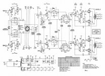
#1: I don't think the preamp section can possibly be working right based on some measurements against the schematic. I don't know how to overall test it since I don't have a turntable. It looks like V1 and V2 are the preamp? Some of the resistors are a different value from the sch.
pin resistance values:
V1 (12AX7)
Theor. actual
pin 2 6..8M (340k)
pin 3 0 (0)
pin 7 5.7k (59k)
pin 8 3.3k (3.3k)
V2 (12AX7)
pin 2 6.8M (358k)
pin 3 0 (0)
pin 7 5.7k (59k)
pin 8 3.3k (3.3k)
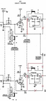
V3 (12AX7)
pin 2 700k (900k)
pin 3 1.8k (1.8k)
pin 7 700k (750k)
pin 8 1.8k (1.8k)
V4 (12AX7)
pin 3 300 (300)
pin 8 300 (300)
V5 (12AU7)
p2 1M (1M)
p3 23k (23k)
p7 1M (1M)
p8 23k (23k)
Here are the voltages greater than 10% off:
V1
p1 140v (103v)
p6 80v (126v)
p8 .75v (.97v)
V2
p1 140v (265v)
p6 80v (111v)
p8 .75v (0v)
should I go through and just replace all the resistors with metal film original values? Or is there a legit reason for these being far off. I noticed the monolithic circuit thingy was replaced with individual components just in the preamp section. Also, should I unplug the V1 and V2 since I'm on the phono Hi input to protect them while figuring this out?
thanks
I'd like to clean up a few things then maybe rebuild the amp and build a wood cabinet for it.
ok, one issue at a time:
#1: I don't think the preamp section can possibly be working right based on some measurements against the schematic. I don't know how to overall test it since I don't have a turntable. It looks like V1 and V2 are the preamp? Some of the resistors are a different value from the sch.
pin resistance values:
V1 (12AX7)
Theor. actual
pin 2 6..8M (340k)
pin 3 0 (0)
pin 7 5.7k (59k)
pin 8 3.3k (3.3k)
V2 (12AX7)
pin 2 6.8M (358k)
pin 3 0 (0)
pin 7 5.7k (59k)
pin 8 3.3k (3.3k)
V3 (12AX7)
pin 2 700k (900k)
pin 3 1.8k (1.8k)
pin 7 700k (750k)
pin 8 1.8k (1.8k)
V4 (12AX7)
pin 3 300 (300)
pin 8 300 (300)
V5 (12AU7)
p2 1M (1M)
p3 23k (23k)
p7 1M (1M)
p8 23k (23k)
Here are the voltages greater than 10% off:
V1
p1 140v (103v)
p6 80v (126v)
p8 .75v (.97v)
V2
p1 140v (265v)
p6 80v (111v)
p8 .75v (0v)
should I go through and just replace all the resistors with metal film original values? Or is there a legit reason for these being far off. I noticed the monolithic circuit thingy was replaced with individual components just in the preamp section. Also, should I unplug the V1 and V2 since I'm on the phono Hi input to protect them while figuring this out?
thanks
Attachments
Pin 2 low resistance could be dirt combined with dampness on the valve sockets or the valve itself. Or it could be the 6.8M resistor has gone low.ppavone said:pin resistance values:
V1 (12AX7)
Theor. actual
pin 2 6..8M (340k)
pin 3 0 (0)
pin 7 5.7k (59k)
pin 8 3.3k (3.3k)
V2 (12AX7)
pin 2 6.8M (358k)
pin 3 0 (0)
pin 7 5.7k (59k)
pin 8 3.3k (3.3k)
Pin 7 should be 57k, so 59k is fine.
V1 voltages are not too far off. If that channel works OK then don't worry. 20-30% error is usually OK for valves.Here are the voltages greater than 10% off:
V1
p1 140v (103v)
p6 80v (126v)
p8 .75v (.97v)
V2
p1 140v (265v)
p6 80v (111v)
p8 .75v (0v)
V2 may be faulty. Try swapping it with V1 and re-measure voltages. See if the faults move or stay.
The first task is to fix what is broken. Changing everything is as likely to introduce new faults as fix old faults.should I go through and just replace all the resistors with metal film original values?
The 6M8 is what it has to be, the tubes get there bias voltage from the grid current in those resistors.Best replace also the 10nF capacitors there.
The voltages in the schematic don't agree with the data sheet.
And your measurement look like from worn out tubes.(or heater voltage to low)
Mona
The voltages in the schematic don't agree with the data sheet.
And your measurement look like from worn out tubes.(or heater voltage to low)
Mona
Attachments
> V1 p1 140v (103v)
> V2 p1 140v (265v)
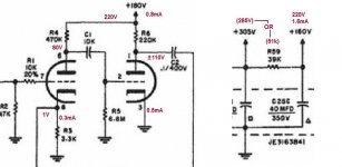
V1b/V2b is grid-leak bias. The exact plate current will vary a LOT with different tubes. In general the tube will adjust itself to a high-gain condition, which is what we want. The exact plate voltage should not be very critical, because signal level here is still small.
103 vs 140 is not to worry.
265V for 140V is clearly quite wrong. V2b is not sucking current. Suggest bad contacts. Also as-said, move tubes around: either trouble moves with tube, trouble stays where it was, or trouble vanishes (bad contact due to tarnish, "fixed" by working pins in sockets).
265V is double-odd because plan shows only 180V going to this section. "Dead" V2b explains some of that rise, and I suspect the voltages and parts on the plan are very approximate to how it got built and how it really works.
I would NOT rush in with wholesale part replacement. Tarnished tube and switch contacts, bad tubes, leaky caps... start with the things that do go bad with age.
For a console, this is a very deluxe design.
> V2 p1 140v (265v)
V1b/V2b is grid-leak bias. The exact plate current will vary a LOT with different tubes. In general the tube will adjust itself to a high-gain condition, which is what we want. The exact plate voltage should not be very critical, because signal level here is still small.
103 vs 140 is not to worry.
265V for 140V is clearly quite wrong. V2b is not sucking current. Suggest bad contacts. Also as-said, move tubes around: either trouble moves with tube, trouble stays where it was, or trouble vanishes (bad contact due to tarnish, "fixed" by working pins in sockets).
265V is double-odd because plan shows only 180V going to this section. "Dead" V2b explains some of that rise, and I suspect the voltages and parts on the plan are very approximate to how it got built and how it really works.
I would NOT rush in with wholesale part replacement. Tarnished tube and switch contacts, bad tubes, leaky caps... start with the things that do go bad with age.
For a console, this is a very deluxe design.
For a console, this is a very deluxe design.
The OP had a positive experience with a low power console amp. That prompted the acquisition of the H/K A300.
------------------------------------------------------------------------------------------------------------------------------------------
The 7408 O/P tube is the industrial version of the 6V6. New Sensor's "reissue" TungSol 6V6 is a highly suitable replacement for the 7408.
H/K, along with several other manufacturers, used the "Cheap Charlie" method for DC heaters in the low level magnetic preamp section. The method SUCKS.

 Those heaters are employed as the resistance of the O/P tube bias network. A single network is shared among all 4 O/P tubes, which requires that replacement O/P tubes be acquired in tightly matched quads and that raises costs. Another big downside to "Cheap Charlie" is that the O/P signal modulates the current flowing in the preamp tube heaters.
  Long term, construct a proper, regulated, 12 VDC supply for the mag. preamp tubes and insert a pair of RC O/P tube bias networks (1/channel), which allows the use of 2X matched pairs of O/P tubes.
Tape head I/Ps are passe in today's environment and switches in mV. level signal lines are a source of problems. The low level mag. preamp section should be permanently configured for RIAA and hard wired to a single pair of RCA jacks All other I/Ps should be at line level. A 2-6 position (user selectable) replacement source selector (Lorlin brand) can be obtained from Mouser for approx. $5.
Attachments
Like Dak808 says,those resistances can be very different that what the published specs are. Keep mind that many of these readings are predicated on the residual charge or condition of the filter caps at the time. Also,where your reference point of measurement is can change readings as well. I would check DC voltages of the unit and then go from there.If you want to check resistors for actual readings,it is best to open one side so nothing influences the reading but the resistor. If you taking resistance of the circuit,those will vary because of the filter caps. Even turning your meter leads around can make those readings vary quite a bit. I would completely discharge the filter caps and then you will get a closer reading.
Some points about what's seen in these photos.
1. While H/K used good quality laminations in the O/P "iron", the trafos are (overall) a bit lacking in mass. Take it somewhat easy in the bass demands you place on the amp or convert to triode mode "finals" mated to mid 90s sensitive speakers.
2. Notice the electrolytic cap. sleeved in cardboard. That cap. is part of the voltage doubler B+ PSU stack and must be isolated from the chassis. Modern, plastic sleeved 'lytics can be clamp mounted in the holes occupied by the OEM parts. For a "warm, fuzzy, feeling", you can add heatshrink to the manufacturer supplied sleeving.
Jim McShane is EXPERT in "the care and feeding" of H/K voltage doubler PSUs. I strongly suggest you discuss your needs with him.
Some points about what's seen in these photos.
1. While H/K used good quality laminations in the O/P "iron", the trafos are (overall) a bit lacking in mass. Take it somewhat easy in the bass demands you place on the amp or convert to triode mode "finals" mated to mid 90s sensitive speakers.
2. Notice the electrolytic cap. sleeved in cardboard. That cap. is part of the voltage doubler B+ PSU stack and must be isolated from the chassis. Modern, plastic sleeved 'lytics can be clamp mounted in the holes occupied by the OEM parts. For a "warm, fuzzy, feeling", you can add heatshrink to the manufacturer supplied sleeving.
Jim McShane is EXPERT in "the care and feeding" of H/K voltage doubler PSUs. I strongly suggest you discuss your needs with him.
Exactly Eli. I hate when they derive DC for the filaments from some half *** unfiltered method. Another good example of this was on the Eico HF87 where they put DC filaments on the 12AX7 voltage amp,taken off the cathode of the right channel EL34.They use a 235ohm cathode resistor on one side and a 165 ohm resistor in series with the filament of the 12AX7 on the other side. You don't need DC filaments on that tube in an amp and I just eliminate it and parallel the AC filaments to 4,5,and 9.
You are right about the iron in this HK amp.If he doesn't saturate the iron from going too low in frequency,he can get more usable power. If you notice, it has a reasonably good driver with the 12AU7 and the 12AX7 voltage amp. I'm surprised they went for 470k grid resistors tho.That is running pentode and that driver circuit can ease thru that.Do the grid leaks need to be that high?
There is a lot of good advice headed your way in the posts above. Let me help you out a little bit...
1. Measure the voltage on pins 4 and 5 of v1 and v2. You need to see somewhere between about 11 and 13 volts there. As Eli posted, the heaters of the 12AX7s are powered by the current through the output tube cathodes. It works but you can do much better. Nonetheless be sure it is delivering somewhere near 12 volts DC from pin 4 to pin 5 in each tube. If the voltage is too low the 7408/6V6GT tubes may be tired. Let us know what you find.
2. Test or swap V1 and V2 for known good tubes if you get proper heater voltages. Clean the sockets well to ensure good contact - the tube pins too. I won't be surprised if this step fixes the voltage problems! Also, you can find good cleaning info here: https://www.audioasylum.com/messages/tubes/253369/
3. If you are measuring resistors and want to be more confident in the results you may need to lift (disconnect) one end so that the resistor is not in the circuit when you measure it.
4. I think you may have a measurement error on the V1 and V2 pin 7 measurements. It should be about 57K and the fact that you read 5.7K on both resistors (1/10th of the correct value) makes me think you misread your meter or such. Of course - being a big time expert I've never made that mistake.
5. Just replace the 6.8 Meg resistors. They aren't expensive and the new metal film resistors are very quiet. Really after 50 years MOST small wattage carbon composition resistors are ready for replacement. The same is true for the capacitors in the unit - they are well past their normal lifespan.
Keep in mind you are probably encountering multiple problems. Solving one may not solve them all - but you have to start somewhere. I think that you have a usable game plan using the steps above.
Let us know what the results are from these checks!
great help.
I'll plan on keeping any replacements to a minimum.
I see the preamp is a cathode follower. So there is something I'm not quite getting. I know the cathode supplies the signal to the RC tone stack. But then it joins back up with the signal off the plate. Won't this cause a phase shift between the two signals? One through an RC network and one not? Or at least "wash out" the effect of the tone controls being that the signal off the plate is at a much greater potential? I'm probably way off here and not thinking of something but it's been bothering me.
thanks again
I'll plan on keeping any replacements to a minimum.
I'll do that. I will also replace the electrolytics in the cans. Can't seem to pin down a replacement for the (50/100/200). Any sources I should check?Best replace also the 10nF capacitors there
these are off the schematic, so I assumed it was for "in-circuit" measurement? Is that not correct?Hi P, You do realize that measuring resistors in circuit can give you very different values unless one of the resistor leads is detached? So, the ones that are way off might just be because you are reading the resistance of more than that single one.
The amp came with 6V6 O/P tubes.The 7408 O/P tube is the industrial version of the 6V6. New Sensor's "reissue" TungSol 6V6 is a highly suitable replacement for the 7408.
I'd rather keep the amp in it's original configuration as I will most likely pass it on as I move to another amp.The low level mag. preamp section should be permanently configured for RIAA and hard wired to a single pair of RCA jacks All other I/Ps should be at line level. A 2-6 position (user selectable) replacement source selector (Lorlin brand) can be obtained from Mouser for approx. $5.
I see the preamp is a cathode follower. So there is something I'm not quite getting. I know the cathode supplies the signal to the RC tone stack. But then it joins back up with the signal off the plate. Won't this cause a phase shift between the two signals? One through an RC network and one not? Or at least "wash out" the effect of the tone controls being that the signal off the plate is at a much greater potential? I'm probably way off here and not thinking of something but it's been bothering me.
thanks again
I will also replace the electrolytics in the cans. Can't seem to pin down a replacement for the (50/100/200). Any sources I should check?
As I previously stated, discuss your needs with Jim McShane. He'll fix you up with parts that will get the job done. The available selection in multi-section can caps. is not large, compared with the past. Fortunately, modern 'lytics are much more volumetrically efficient than the old stuff and they also exhibit lower ESR/ESL.
IMO/IME, clamp mounted parts for the doubler stack are the way to go.  Work the rest out with Mr. McShane's assistance.
Along with the old, dried out, 'lytics, the OEM doubler diodes need replacement. The 1960s diodes are NOISY.
Sorry, maybe I wasn't clear. The resistor values I originally posted were from the "resistance readings" table at the bottom of the schematic. Not individual resistor values.The values next to the component are component values not in-circuit measurements.
Now to the workshop to get measuring!
so I'm reading 24v-11.4v-11.5v-0v going from 4-5-4-5. So heaters look good.be sure it is delivering somewhere near 12 volts DC from pin 4 to pin 5 in each tube.
yup, typo on the original post: pin 7 and 8 are 59 ohms
the high voltage (265v) follows one of the tubes on pin 1. So must be it's a bad tube?
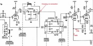
Yesterday i wrote that there is an error in the schematic, but it was me 
Well it was late over here and the schematic is a mess
They draw a NFB loop around the rumble filter, like that the result of the filter is compensated by feedback, no filter !
I suspect the real amp is wired like this ...
Mona
Well it was late over here and the schematic is a mess
They draw a NFB loop around the rumble filter, like that the result of the filter is compensated by feedback, no filter !
I suspect the real amp is wired like this ...
Mona
Attachments
HK-A300 is a wonderful little amp that has lively sound very distinct from bland sound of contemporary Scott, Eico, or Bogen pentode amplifiers. I won't bet my money on it, but I believe that PFB is what gives this amp its character. It has great MM phono section.
The output transformers are indeed smallish, and deep bass is lacking, though adequate for most classical music.
I don't think using 12AX7 series heaters as common cathode resistor has any problem. Due to PP design, there isn't much signal on the cathode resistor to have any influence on upstream stages. Moreover, the cathode resistor is bypassed by a 200 uF capacitor, which wipes out any residual signal.
The amp has certain flaws. The most important problem is slider switches developing bad contacts. Since these switches are functionally useless, the best fix is to short the appropriate contacts. The main rotary switch is OK. Pots may also go bad, and if they are scratchy, they should be replaced with modern Alps. Surprisingly, electrolytes in power supply may not necessarily need replacement - at least try to reform them first. However, old paper capacitors may become leaky, and should be replaced, preferably with teflons.
6V6 tubes may not be suitable for this amplifier due to their low screen rating. If you have to use them, at least use the GT variety. 7408 is adequate. I have been using Russian 6P6S for many years with no problems.
One mod that I would highly recommend is a choke in screen supply. Gives very noticeable improvement.
Last edited:
what does PFB stand for?but I believe that PFB is what gives this amp its character
would you recommend all four GT be a matched set as stated earlier?6V6 tubes may not be suitable for this amplifier due to their low screen rating.
what size and where would it go? Right off pin 4 of the O/P tubes?One mod that I would highly recommend is a choke in screen supply
what does PFB stand for?
Positive feedback. The amp has PFB through common cathode resistor R22 (300 Ohms) of V4 and V5.
[/QUOTE]would you recommend all four GT be a matched set as stated earlier?[/QUOTE]
Matched tubes are must for this amplifier. This is not a problem though. You can buy a matched quad of 6P6S for $32.
[/QUOTE]what size and where would it go? Right off pin 4 of the O/P tubes?[/QUOTE]
Choke should replace the 470 Ohm resistor in the power supply. It should be 5-10 H with DCR of 400-700 Ohms and rated for 50-70 mA DC.
I agree with the choke idea. A choke in the g2 B+ supply improves regulation and reduces ripple. Well regulated g2 B+ maximizes the open loop linearity of full pentode mode "finals". Jim McShane incorporates a choke in his upgrades for the H/K Cit. 5, which also employs full pentode mode O/P tubes.
Approx. $10 buys a Triad C-3X from Mouser and that part matches the spec's sser2 provided.
Approx. $10 buys a Triad C-3X from Mouser and that part matches the spec's sser2 provided.
- Status
- This old topic is closed. If you want to reopen this topic, contact a moderator using the "Report Post" button.
- Home
- Amplifiers
- Tubes / Valves
- New tube DIY'er with an HK A300