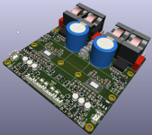
As a many years happy user of TPA3255, I thought it might be a good time for an upgrade. So here it is:


It's a dual mono, PBTL, single power supply design with PFFB. 12V is generated internally with two LM5017. It uses standard heatsinks available from Mouser:
https://www.mouser.be/ProductDetail/984-ATS-TI1OP519C1R3
but they do need to be shortened at one side to fit them both on PCB.
Board is 4-layer 10x10cm standard thickness. Coils are CoilCraft SER2918 mounted vertically.
Last edited:
It was not critique of your board, just a technical question.
Even if there is some DC at the output of the 1656, the amplification is only x1. The input of the 3255 has another 10uf DC blocker anyway. So I ask if there is another reason, other than the DC for this capacitor.
Even if there is some DC at the output of the 1656, the amplification is only x1. The input of the 3255 has another 10uf DC blocker anyway. So I ask if there is another reason, other than the DC for this capacitor.
im also curious of c17/c52, i have been using it in similar way also without that specific cap for quite some time, if cost and pcb space is not issue is there any improvement? better characteristics when overdriven input? faster settling time if dc gets in or low freq signals?
edit, also m2 with 10k on to VDD closeby works, why to dvdd? dvdd sometimes can be problematic if cap is not direct to nearby gnd.
edit 2, also not needed to pull reset high.
edit, also m2 with 10k on to VDD closeby works, why to dvdd? dvdd sometimes can be problematic if cap is not direct to nearby gnd.
edit 2, also not needed to pull reset high.
Last edited:
I don't think there is any audible effect from the cap, as long as you use some film type, not something questionable. There are numerous perfect sounding amp /preamp builds that have a dozend or more DC blockers and have no problems.
When DIYS amps got better, at some point the use of cheap electrolityc input caps got audible. Sound improved when they were bridged and the input DC coupled. Good industry quality film caps solved the problem of audiability and keept the DC protection.
When DIYS amps got better, at some point the use of cheap electrolityc input caps got audible. Sound improved when they were bridged and the input DC coupled. Good industry quality film caps solved the problem of audiability and keept the DC protection.
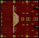
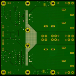
I think that 4 layer board is a bit of an overkill, so I decided to play around with dual sided one. Here is the result that worked out just fine I guess. I also removed those two extra caps and reset pullups. I'm controlling reset signal with MCU anyway.
Attachments
Last edited:
nice, if not already in production, it would be more safe approach to put vcc caps closer to chip power pins as gate drive caps(33nf) are not so much sensitive if there is a bit distance in traces, i have tried many approaches for pbtl 2 layer and is always those caps that are problematic fit when paraleling before filters.
im curious if anyone tried to bring external voltage to those bst pins? it would for sure make pbtl easier or to say better cleaner 2 layer layout, it would just need some simple logic that shuts off those vregs when fault is present and some vregs have enable pins anyway.
anyway i might try that on next pcb as for what i want with power delivery right now changed from before and will simply not fit on 2 layer.
also maybe better to put ground under unfiltered output as to not make antenna.
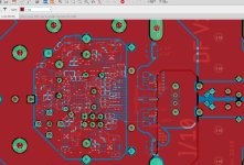
to better try to show what i mean i attached picture of my old approach with 0805 33nf caps sort of not in a way but still close to pins, this works in pa duty speakers for some years now without issues on high powers/voltages. but single chip single pcb only mistake is with dvdd filtering on this picture, its too far away and should be long side towards tpa i bodged it like that later and it works...
cheers.
im curious if anyone tried to bring external voltage to those bst pins? it would for sure make pbtl easier or to say better cleaner 2 layer layout, it would just need some simple logic that shuts off those vregs when fault is present and some vregs have enable pins anyway.
anyway i might try that on next pcb as for what i want with power delivery right now changed from before and will simply not fit on 2 layer.
also maybe better to put ground under unfiltered output as to not make antenna.
to better try to show what i mean i attached picture of my old approach with 0805 33nf caps sort of not in a way but still close to pins, this works in pa duty speakers for some years now without issues on high powers/voltages. but single chip single pcb only mistake is with dvdd filtering on this picture, its too far away and should be long side towards tpa i bodged it like that later and it works...
cheers.
Attachments
Thanks. We all know they should be "as close as possible", but how close, nobody knows") Another thing now that you mentioned this, it does not seem to be a reason to have 4 PVDD coupling caps as seen on schematics, since there are only two in EVM user guide layout recommendation for PBTL (T2):
Another thing now that you mentioned this, it does not seem to be a reason to have 4 PVDD coupling caps as seen on schematics, since there are only two in EVM user guide layout recommendation for PBTL (T2):


Another thing now that you mentioned this, it does not seem to be a reason to have 4 PVDD coupling caps as seen on schematics, since there are only two in EVM user guide layout recommendation for PBTL (T2):
Last edited:
yes two but on chip pins, i assume it is more relevant when using chip as SE mode, but either way 33nf cap you are sure you can fit further away but pvdd im not so sure. i did put 4 on relative high distance on my pcb, but still have 2 direct on pins, i never got around testing it without caps near pins, as i found a different solution for mounting it on heatsink so height of capacitor was not that big of a issue. i did test it and working ok different pcb with bulk electrolytics located somewhat far away on other aka main pcb but with ceramics on pins and few more nearby on same pcb. im curious for results. have a nice day.
- Home
- Amplifiers
- Class D
- New TPA3255 dual mono in PBTL