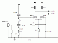
Don't understand. Newbee to tubes. You say it is a long tail, but it looks like the output of one is sent to the second. Would that not be a paraphase splitter, followed by a diff pair? I thought a long-tail relied on an RC phase delay feeding the second grid to get the non-inverted output.
Much more clear. I was confused thinking V1 was the splitter and V2 a dif driver.
There does seem to be a lot of creative in tube schematics. I'll learn. Thanks
I do not understand why the plate resistors are different values. Why?
Next I guess I need to understand the why one selects one topology for another. Through the forum I found a "idiots guide to tubes" which helped quite a bit on splitters. Lots talking about output stages, the religious war on SE vs PP, but not much on input stages and buffers. Downloading every schematic I can, I do start to see trends in cheap, my Meng, or highly respected, VTL. It seems layout and execution is more critical than solid state. Just starting to have enough basics to look at data sheets. I see a lot of comments like "6N1's like more current". I am guessing that would show up as where they are more linear in the curves.
Good question. If the phase splitter was attached to an large cathode resistor, which was attached to an negative supply rather than ground, the value of the cathode resistors would be equal. This is the designers way to compensate for the less than perfect phase splitting in this design.I do not understand why the plate resistors are different values. Why?
A CSS (Constant Current Sink) can replace the cathode resistor and come very close to a "perfect" resistor with finite DC resistance and large AC ( Order of mega-ohm for well designed CCS at audio frequencies)
I do not understand why the plate resistors are different values. Why?
Also check out the last paragraph of page 7 and top of page 8 from Claus Byrith
http://www.lundahl.se/pdfs/claus_byrith/amplifier_30wpp.pdf
Just printed that one. Been grabbing every schematic I can find and trying to work out the "wisdom" of one option vs another. Unfortunately, many designers omit or publish incorrect values to protect their design, which makes it hard to use them for learning. Time fore some serious calculator work.
I planned on hacking up my Meng as a test chassis, but it is hard and cramped to work on. I have an HK A 300, but it is considered a classic, so I hate to hack it up. (sounds like garbage, so I may anyway). Been so long from tech school, I have not had the fun of "Apply power and tune for minimum snoke" for a long time. Solid state is just not as "exciting".
I planned on hacking up my Meng as a test chassis, but it is hard and cramped to work on. I have an HK A 300, but it is considered a classic, so I hate to hack it up. (sounds like garbage, so I may anyway). Been so long from tech school, I have not had the fun of "Apply power and tune for minimum snoke" for a long time. Solid state is just not as "exciting".
- Status
- This old topic is closed. If you want to reopen this topic, contact a moderator using the "Report Post" button.
- Home
- Amplifiers
- Tubes / Valves
- New to Tubes, just bought first tube amp
