OK I am brand new here and just starting out so I will apologize if I am in the wrong area for this post. I just received an old Heathkit amplifier from a friend of mine that scraps metal. I told him I was looking for and old tube amp to tinker with and 3 months later he drops a heathkit ea-2 on me for free. It is missing a tube but other wise looks pretty good. I want to get started on getting the amp working and read a few articles about replacing electrolytic caps and coupling caps. I have NOT attempted to plug the unit in and figure it would not work anyway being the EZ81 tube is missing. I have never worked on a tube amp before and have repaired some solid state amps before. I have limited knowledge of electronics. I know what a resistor, capacitor, transistor, etc look like and have some knowledge of what they do but lack full understanding of what makes the entire circuit work. I got a schematic online and believe I have identified all the caps the need replacing. While I had all the tubes out I decided to run a few quick tests and already think I have a problem. The resistance between the Blue/yellow and Green/Yellow measures 83.2 ohms and the resistance between the Green and Blue measures 129.1. From what I see these are connected to pins 7 and 9 of each EL84 tube in a push-pull. I would assume the the resistance should be the same between each because if not a sine wave would be unbalanced leaving the top half of the wave with less or more amplitude then the bottom half. So I have a few questions. 1) is my assumption correct that the output transformer needs to be replaced? 2) if so where would I purchase a suitable output transformer? last question and probably the most important. Is this amp worth the time and effort? I don't mind the time and expense as I am learning but would rather spend the time and effort on something that will give me years of listening pleasure would this be classified as a good HIFI amp especially if I can get another one and run them for stereo. I see a lot of people talk about the Heathkit Williamson and open ended amps. There is a lot going on for a newbie like me any help suggestions would be appreciated
I don't have the heathkit schematic, but in most 6BQ5/EL84 circuits the plates (pin 7) each go to an output transformer winding, and the center tap of the primary of the output transformer goes to one of the high voltage pins of the big B+ capacitor. You may have to lift the wire off the capacitor to get a good resistance reading, as these old capacitors are often shorted, or measure partially shorted until "reformed". The first step of "reforming" an electrolytic capacitor is put the plus of the ohms scale on the pin, the minus on the chassis, and run it until the resistance is infinity.
a good source of transformers for EL84/6BQ5 is the ST35 replacement output transformer sold by triodeelectronics.com in Illinois. Or maybe SCA35, whatever. The old dynaco 6BQ5 tube power amp.
Pins 9 of the El84/6BQ5 should go through a resistor (each tube) to a lower voltage tap on the B+ capacitor, going by the Hammond AO39 schematic anyway.
any metalwork will get you started on a tube amp. Heathkits had a little cheaper input connectors and volume pots than a dynaco, but those probably have to be replaced anyway due to corrosion. Unless your input pot is a centralab or CDE, then start by just cleaning it.
heathkit output transformers weren't as good as dynaco's either IMHO, but then, if you're going to replace it, go for the 1960's standard, right off. Dynaco bought premium plate coupler caps, most of mine are still good. I don't know what grade coupler cap heathkit used but suspect they were cheaper. Guitar amp people always replace all the paper dielectric plate coupler caps on their old amps, those tended to be really cheap. Measure your resistors before powering up, too, a lot of high value ones (over 3 k) might have gotten water soaked and increased in value. I use metal film resistors these days, 2 and 3 watt ones for the voltage rating.
EL84 amps are about 13 W/channel, so to really enjoy it you'll need a very efficient speaker. My SP2-XT's are 101 db@1 W @1 m, which is about as sensitive as they come.
With point to point wiring, and a drill to mount a bigger power transformer and punch 7/8" holes for the octal sockets, you could eventually upgrade to EL34/6CA7' s some day and go for 35 W/ch. classicvalve.ca has got some driver boards you could mount on standoffs instead of punching a dyna sized hole.
But making this thing work is great training. Don't use two hands to measure tube voltages, current across your heart over 24 v can stop it. Use a clip lead on the meter negative and one hand. don't work tubes alone. Don't work tubes distracted by television or a cell phone. use a lot of light. Read the safety sticky at the top about measuring discharging electrolytic capacitors to a safe voltage before touching any metal under the deck.
Have fun.
Last edited:
First off, the voltages in a tube amp can KILL YOU, so please be very careful, and never assume a cap is discharged.
Thee transformer works on turns ratios, not resistance. There are two ways to wind a center tapped transformer. One is to start with wire, and wrap half the turns around the form, then attach a tap wire, then wind the remaining half of the turns. This results in one side of the transformer wound around th small core, while the other side of the winding is wrapped around the first half. The result of that is that the second half wire has to go farther to make one turn than the inner windings. Wire has resistance by the foot, so if there is 50% more wire for a number of turns, the resistance will also be 50% higher. (I made up the percents.)
The other way is to use two pieces of wire - one for each half - and wind them at the same time. When done, we join two of the ends to make a center tap. That results in both halves making the same path around the core, and the winding resistance will be even.
Both methods work, because as I said, transformers work on turns ratios. The first method is cheaper to make.
SO, no, I don't think your transformer is bad, and I think you do not have to replace it.
Generally, when transformers fail, it is by shorting a couple turns together or shorting to frame. And of course they can also arc. If you have two adjacent turns short together, your meter would never detect it. A short to frame you can measure. An arc only occurs at high voltage, so your meter cannot detect that either. What doesn't happen is transformers wholesale changing their wire resistance. I am sure there are exceptions to any rule of thumb, but like the wise man says, "When you see hoof prints in the dirt, think horses, not zebras."
When the circuit is not powered, the center tap is really the only part connected to anything. The ends of the winding connect to tube plates, which are just pieces of metal sitting in a vacuum. So to measure the primary winding resistance and resistance from ends to center tap, you really don't need to disconnect anything.
Worth? Well, the thing cost you nothing, right? SO if you screw it up, at least you didn't spend a couple hundred bucks on a kit. I doubt your transformers are an issue. If I wind up wrong, well, sorry, but I don't think so. That means you are buying caps and resistors and maybe tubes. Mostly inexpensive stuff. The experience translates, amps are amps. Larger tubes and higher voltages and currents don't change the basic underlying circuit structure. YOu can learn a lot about amps working on this thing. And they are nice enough little amps.
Welcome to the board with all of us crazies. What you have is a nice little audio amplifier that's good for about 10 to 12 watts and a good place to start learning. I will say that the output transformer is most likely OK. What you are measuring is DC resistance of the primary that gets physically larger as more wire is added. This means that it requires a longer length of wire to make the same number of turns as the "coil build" gets larger. This is normal.
Now it could be that the transformer is still defective, but you will not really know this until you get it going or make further tests. Having continuity between the five primary wires is good. There should be no measurable resistance between the primary and secondary and/or the steel core. That would mean a short.
Many on this forum will say the replace all the filter capacitors as a matter of course. (I have a slightly different opinion regarding this, but after fifty plus years of repairing electronics what the h*ll do I know.) This includes all electrolytic capacitors in general. In your amp these are C1-2 & 3 (the big metal can) C4, C32 (if there) & perhaps even C30. C16 & 19 should be checked for leakage once you get it up and running.
Is restoring this amp worth it? It's really up to you. If the amp is clean and you like it, then yea sure because it was free.
Attachments
Last edited:
That the 6CA4/EZ81 rectifier is missing is not a surprise. The type is highly desirable. The schematic H/S uploaded is interesting, as it shows a 6BW4 being suitable. Unless you source a 2nd EA-2 specimen, investing the minimum amount of money in a learner project seems correct. A look at Jim McShane's site shows a new 6CA4/EZ81 costing $19.50 and a new 6BW4 costing $5.50. Buy a 6BW4! 
While it may be possible to reform the "ancient" electrolytic caps., it is a fact that modern 'lytics are superior. Also, 'lytics literally dry out over time. The "knee jerk" recommendation to replace all 'lytics is made (IMO) for good reason.
While it may be possible to reform the "ancient" electrolytic caps., it is a fact that modern 'lytics are superior. Also, 'lytics literally dry out over time. The "knee jerk" recommendation to replace all 'lytics is made (IMO) for good reason.
Thank you all for the great information. I do not have any measurement between any primaries to any secondary. I also did not have any readings from any of the taps to ground so and I do have different readings between all the wires and center tap. I do understand the voltages present and will discharge all with a resistor jumped between each before working on the amp. I have 4 children and do plan to stay alive. I also heard that jumping a 1k resistor from ground to the pin 1 on the 12AX7 socket for about 2 minutes wold thoroughly bleed all Caps. With that said I think I am going to dive in. I just ordered another EA-2 from ebay. I paid 87 for it plus shipping for a total investment of 103.00 for 2 amps to start with. I downloaded a few book from tubebooks.org to start learning how the circuits work. It will take a while but I will get there. I have about 30 years of soldering experience as my father and I would build healthkit stuff when I was younger. Together we built a 5 inch black and white TV, a solid State stereo and a few resistor and capacitor substitution boxes. Currently I repair all kinds of stuff for family. I have more of a mechanical aptitude than electronic but have tons of pulled stuff from old PC power supplies, printer power supplies etc. I gut everything. I have a Fluke meter with capacitance ability. I am thinking of gutting both amps. Checking all resistors for proper values recapping with some sprague orange drops for coupling and substituting sprauge atoms for the electrolytics. I do have a quick qustion. the 4 capacities listed on the can are 450 at 30mf, 400 at 20mf, 350 at 20 and 300 at 20. Can I replace all with 450 33mf? Does the voltage rating change anything in the circuit? I would think that you could always substitute a higher voltage without any issue but that has always worked with low voltage DC circuitry. Also i read that is is OK to go higher on the MFD rating as long as you don't exceed an 80% rise of the recommended value. Are these safe assumptions. Also I see some talk abut the russian 40-y PIO caps for coupling. Any thoughts as to recap with sprague orange drops or the russian PIO
With vacuum rectifiers, there are published limits on the value of the 1st filter capacitor. Exceed the published limit and you risk arcing at turn on. Turn on arcing can destroy a vacuum rectifier.  The 6CA4/EZ81 data sheet is here and the 6BW4 data sheet is there.
Acquiring a 2nd specimen means you are deadly serious about tubed stereo music reproduction. IMO, Heath's circuitry has serious flaws. For instance, the tuner I/P and the, currently useless, piezoelectric cart. I/P are substantially attenuated before being fed into the 2nd gain block of the mag. phono preamp. Are you planning on a simple overhaul or is upgrading of circuitry under consideration? Is there somebody local who can mentor you, along with this forum's members?
Both 716P series "Orange Drops" and Soviet surplus PIO parts are quite satisfactory. Mixing the 2 "flavors" up could easily yield the best end result.
The 6CA4/EZ81 data sheet is here and the 6BW4 data sheet is there.Acquiring a 2nd specimen means you are deadly serious about tubed stereo music reproduction. IMO, Heath's circuitry has serious flaws. For instance, the tuner I/P and the, currently useless, piezoelectric cart. I/P are substantially attenuated before being fed into the 2nd gain block of the mag. phono preamp. Are you planning on a simple overhaul or is upgrading of circuitry under consideration? Is there somebody local who can mentor you, along with this forum's members?
Both 716P series "Orange Drops" and Soviet surplus PIO parts are quite satisfactory. Mixing the 2 "flavors" up could easily yield the best end result.
Yes you can.I do have a quick qustion. the 4 capacities listed on the can are 450 at 30mf, 400 at 20mf, 350 at 20 and 300 at 20. Can I replace all with 450 33mf?
In this case no, not at all. Decending voltage ratings in electrolytic capacitors back in the day was more of a size/cost issue. Today that's almost moot.Does the voltage rating change anything in the circuit?
The capacitor directly off the rectifier cathode is the critical one concerning value size. Leave this value close to what it is to prevent start up stress on the rectifier tube. Other values down the line, so to speak, can be doubled or more.Also i read that is is OK to go higher on the MFD rating as long as you don't exceed an 80% rise of the recommended value. Are these safe assumptions.
PIO (paper-in-oil) capacitors use some type of paper as the insulating dielectric that seperates the conductive material inside. Paper is a relatively poor dielectric and produces a capacitor that is "slower" then the more modern plastic dielectrics like polyester, polycarbonate, polypropylene & teflon. This means that they are less able to pass high frequencies easily. The result is a sound characteristic that is slightly different from the newer plastics. One could perhaps call it "tube sound" or a more mellow or vintage sound. It is also subjective to the individual.Also I see some talk abut the russian 40-y PIO caps for coupling. Any thoughts as to recap with sprague orange drops or the russian PIO
Replacing PIO's with plastics in the un-equalized audio stages usually does no harm, and can even be an improvement sonically. (again subjectively) But care must be exercised when replacing them in the equalized phone stage. For you that's C6, C7 & C8. Try to leave these alone if possible because changes here can upset the playback RIAA curve. The values chosen here could be based on the dielectrics used at the time of manufacture. This is a fine point in audio, and Heath may not have done their design work that carefully in this area. Still, try not to mess with them.
Sorry about the bad info on the unbalanced output transformer turns resistance. The ones I have measured have had equal resistance, but they weren't heathkit.
I replaced .20 uf paper caps with .22 polyester caps in my 1961 built PAS2 preamp, and ended up with a circuit that was too trebly; I have to turn the treble cut control down. So maybe paper caps would be a better choice. Maybe a .018 uf cap parallel to a .0022 cap would solve the problem,too but it is not my highest priority project now.
Modern metal film resistors (over 100kohm) did reduce the hiss in the PAS2 some. None of my 1961 resistors were out of tolerance. the cap that was causing my channel inbalance, had a big burn in the wax case carefully hidden on the bottom where I didn't see it until I replaced the tenth capacitor.
Note unwashed flux on kit builds can cause pops and shorts in the 60th year. I washed & washed, finally had to look at the circuit board in the dark to see the pop. It was shorting where I didn't work, ie the kit builder in 1961 left flux on the board. I replaced two 12ax7 tubes for popping in 1971, probably flux was the real problem. DI water is the solution, even 60 years later.
That is a laugh about nearby mentors. Maybe in Philadelphia, certainly not anywhere I have lived. You could join the ham radio club and listen to people gas endlessly about CQ's and 2 meter and DF's and all those stories of the congenitally motor mouthed ham fraternity, or you could work alone. Just the sound of ham radios offended my ears; my Father's Foley's FM radio actually was the first radio that had a bit of decent sound. I got a bit of education from the dynaco build manuals, a few tips from the MacIntosh salesman at their "clinic" at a hifi store. The RCA Radiotron handbook at the library was pathologically (radiologically?) interested in radio, oscillators all that stuff. Hurrah, the internet.
Last edited:
OK I am brand new here and just starting out so I will apologize if I am in the wrong area for this post. I just received an old Heathkit amplifier from a friend of mine that scraps metal. I told him I was looking for and old tube amp to tinker with and 3 months later he drops a heathkit ea-2 on me for free. It is missing a tube but other wise looks pretty good. I want to get started on getting the amp working and read a few articles about replacing electrolytic caps and coupling caps. I have NOT attempted to plug the unit in and figure it would not work anyway being the EZ81 tube ....
You can replace the EZ81 with a pair of 10 cent 1n4007 diodes. Solder them across the tube socket. This will raise the voltage up a little but this is mostly a good thing, especilly if you replace al the caps
Don't worry about the unbalanced resistance in the transformer. It is not broken it is just a low-cost transformer. That is the way it's made.
You should not expect low 0.1% distortion form this thing. But it might be under 10% and not sound bad
Build a "dim bulb tester". That is just a light bulb base in series with the AC mains. The bulb is a resisoer that limits current. Run the amp like that at forest here for more detail: Powering Up Your Radio Safely With a Dim-bulb Tester
Wow, great information everyone, thank you all for the great help so far. I am on the fence as to whether actually refurbish the 2 individual amps and try and do a full restore on them, or take the 2 amp kits and build a fresh stereo project using the components I have already acquired. The restored Healthkits would probably be worth more money if I went to sell them but I am not doing this to make money. I am doing this to learn something new and build something with great sound for my vinyl collection. Between me and my father we have about 3500 albums. I searched ebay for output transformer for this amp (the EA-2) and could not quite find one that feeds the B+ voltage int the CT. There are a lot of unmarked and unknown ones out there. But while in my reading room yesterday morning, I was browsing through an old parts Express catalog from 2008 and low and behold output transformers with ct connections. They had both Single ended and PP types listed. The one listed for the EL84 tubes were about $55.00 . Now they have others rated for 6l6GC which cost about 75.00. And they also had some for other tubes KT-66 or maybe KT-88 i forget the exact number but they were over 120.00 a piece. Do you think I could use the larger rated transformers for the el84 tubes. I was thinking if I can use larger transformer now I could later reuse them to build up something on a 6L6 PP circuit. I need to really plan here as I am not flowing with a lot of extra cash, and I do have 2 children in College, so for as much fun this has been for me the last week or so I still have to maintain a certain budget. My ultimate goal in about 1 years time to have learned enough to assemble a fairly Hi quality amplifier, with the parts I acquire during my learning states with these amplifiers. I have read some stuff on single ended circuits but the output transformers for single ended stuff are so expensive. For right now I think I will keep the tube rectifiers if I rebuild the ea-2's but for my next project will probably use diodes instead. I have looked at a bunch of different circuits this past friday and some have diodes and some use tubes for the rectifier section. So i guess my biggest question right now is, if the output transformer from the amp I bough from ebay test dramatically different than the other one in the amp that was given to me than I should buy 2 new ones. Could I replace them both with a higher output transformer rated for the 6l6 or is there something else going on that would make their use detrimental to the sound. 2 EL84 will cost me about 110.00 2 for the 6l6 will cost about 160.00. So I am thinking that maybe spend the 50.00 extra and have the ability to use them in something a little more powerful later. I will keep the old ones if I ever decide to sell off the healthkits so the buyer would at least have the original parts. Also picked up a variac this weekend at a yard sale for 5 bucks, and a tube tester for 2.00. I may need some help on using both as I really haven't looked at them aside from placing into my trunk as I had 2 graduation parties on Sat and spent the entire day with my father yesterday for fathers day. Again I thank everyone for the great input so far. I am excited to begin my journey and maybe one day become a true tube amp guru. I will not be able to reply until next monday the 24th as I will be on a job site all day tomorrow, and then i will be on vaction with my family camping wed thru sunday. I will try to get some pictures of my yard sale items along with the 2 amps I am beginning with so you can see what I am working with so far
With well mated speakers, 12 or so WPC are quite sufficient. Something with a sensitivity in the low 90s is in order. Also, a reasonable flat impedance curve is needed. Tube amps have smaller damping factors than SS amps. A nominal 8 Ω speaker with substantial impedance curve dips should be treated as 4 Ω and its sensitivity reduced by 3 dB.
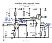
The RCA circuit Heath used in the phono section can be upgraded to be a superior performer. A schematic is attached. Heath used AC heating of the phono stage heaters. If you don't switch to DC heaters, the ONLY current production tube to use is the Sovtek 12AX7LPS. The 'LPS contains a hum bucking, spiral wound, heater and that feature is absolutely essential to having any chance of obtaining an acceptable hum level, when AC heating is used in a phono section.
Look to Edcor for off the shelf "iron". Custom rewinds of failed vintage transformers can be sourced from Heyboer and others, but it can get pricey.
Attachments
I am impressed with the dynaco equipment I found the library using 18 hours a day at my college to play LP's. Triodeelectronics.com is selling copy output transformers made in USA DYNACO Replacement Transformers - MADE IN USA
The 17.5 W output transformer is for 6BQ5/EL84 pairs, the 35 W output transformer is for 6CA7/EL34 pairs. I've bought tubes and other parts from triode, they were fine.
The schematics are all over the internet, as the freeinfosociety versions google can find.
I've got an 8' tall double sided stock shelf full of LP's, plus about 5 storage crates. They are down to $.50 at charity resale shops, and only the rock & roll ones are torn up, usually. I've still got my 1961 dynaco PAS2 and ST70, and a 1970 dynaco ST120 transistor amp. I do recommend new builds of the ST70 use the KevinKR designed (www.classicvalve.ca) triple triode (12AT7) driver board instead of the dynaco 7199 board driver board, since they don't make 7199's anymore. Triodeelectronics.com also has an EF86 pentode driver board for ST70's, okay maybe except the Russian EF86 's are allegedly not as linear as the old Mullard and GEC ones.
Last edited:
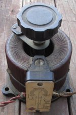
OK I am back from Vacation and looked at the Variac and tube tester I bought last weekend. Tube tester is EICO model 666. Variac is unknown. I have not put test equipment on the Variac yet but the wiring looks quite old, so I may replace with some newer cords. I think for right now I am going to use the 2 Heathkit Amps and run the 2 amps together for stereo. I am looking for improvements to the circuity for these amps as I rebuild them. Being that I am actually going to use them for my listening pleasure when finished I would prefer to make improvements now. I can always restore to original if I went to sell them but as these amps are my first project, I will probably never sell them. Once complete I will continue to listen to them as I build my next tube amp. Eli has made a few suggestions, one was to bypass the rectifier tube with some diodes, This seems easy and a no brainier as these are power supply issues and not actual signal circuitry. I also see Eli's suggestion to convert the heaters to DC to reduce the hum. I would assume a simple bridge with some caps to reduce ripple would work. I will do some research and post my thoughts later to see if I have learned anything. I also saw Eli's suggested circuit posted of a phone preamp but it has a MOSFET in it and I would like to stick to an all tube circuity for the signal path. I will do a little research on the tube tester as I have never used one and this one seems to have a bunch of levers and switches on it. I am attaching photos of the Variac and tube tester. Looking for any links to user manuals for the Eico 666 and any further suggestions for circuit improvements to the Amp without needing to change input or output transformers as I want to keep the iron I have for this first project
Attachments
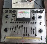
"glendalemanuals" on eBay will sell you a very high quality reprint of your "devil's" tube tester instruction manual which includes the latest set-up data. Well worth the $9.49 w/free shipping asking price.
You already have a few good ideas for improvements. Others might be to switch to a lazer trimed steped volume potentiometer from Alps. If not, add a 1 meg catch resistor from V2's grid to ground should the old control's wiper contact go bad. Also, the FET in the phone stage posted by Eli is there to drive a cable when built as a stand alone unit. If you build it locally on the same chassis you could eliminate it by replacing R3 with a coupling capacitor to the selector switch pin 4.
You already have a few good ideas for improvements. Others might be to switch to a lazer trimed steped volume potentiometer from Alps. If not, add a 1 meg catch resistor from V2's grid to ground should the old control's wiper contact go bad. Also, the FET in the phone stage posted by Eli is there to drive a cable when built as a stand alone unit. If you build it locally on the same chassis you could eliminate it by replacing R3 with a coupling capacitor to the selector switch pin 4.
Last edited:
Also, the FET in the phone stage posted by Eli is there to drive a cable when built as a stand alone stage. If you build it on the same chassis you could eliminate it by replacing R3 with a coupling capacitor to the selector switch pin 4.
True, but if the OP intends to record LPs, the FET is badly needed. The 'X7 triode can't drive anything resembling a serious load.
ok so lets start. The other Heathkit is in. i havent put it on a bench yet. Parts express sells Hammond output transformers made in Canada so if the previous posted values do not match the ebay unit i will probably buy 2 for the el 84 tubes and begin there. i am not looking to record with these amps just listen to vinyl and possibly some flac files from my pc. i would like to stay all tube in the signal path. If i replace the rectifier tube with diodes i would assume i would not have to worry about arcing the tube if i go from 30mfd to 40mfd.. i will rectify the heaters and include a dpdt switch to reverse the polarity from time to time. With these 2 circuit modifications what other improvements can be made to the tube riaa stage with the assumption these units will primarily be used for vinyl listening. I hope to post pictures of both units tomorrow.
OK I am back from Vacation and looked at the Variac and tube tester I bought last weekend. Tube tester is EICO model 666. Variac is unknown. I have not put test equipment on the Variac yet but the wiring looks quite old, so I may replace with some newer cords. I think for right now I am going to use the 2 Heathkit Amps and run the 2 amps together for stereo. I am looking for improvements to the circuity for these amps as I rebuild them. Being that I am actually going to use them for my listening pleasure when finished I would prefer to make improvements now. I can always restore to original if I went to sell them but as these amps are my first project, I will probably never sell them. Once complete I will continue to listen to them as I build my next tube amp. Eli has made a few suggestions, one was to bypass the rectifier tube with some diodes,
THis will raise the B+ voltage by as much as 50 volts. Be sure the capacitors are all rated for the higher voltage. And the tubes too. If the power supply is using an RC filter you can make the R larger to drops the volts back down. This will improve the filter.
With higher B+ volts you will likely have to re bias the power tubes. A really nice mod to make is to and adjustable bias if the amp does not have it already. and then also add a 1 ohm resistor in series with the power tube cathode so you can measure bias current with a volt meter. Then add banna jacks so you can measure volts without getting in to the amp. Youreally should adjust the bias every time you change tubes
This seems easy and a no brainier as these are power supply issues and not actual signal circuitry. I also see Eli's suggestion to convert the heaters to DC to reduce the hum.
There are other, simpler things you can try first. (elevate the entire AC hearer circuit up by about 20 or 50 volts, basically a DC bias is added to the AC. This is almost free, I'd add a bleeder resister to the power supply to drain the caps after power off. Use a voltage divider for that and the center of the divider to bias the heaters. Cost is only two resisters and some wire.
You may not even have a problem. Try powering the heaters with a 6volt battery to see if it helps before fixing a non-problem
I would assume a simple bridge with some caps to reduce ripple would work.
no, you almost always need a regulator for DC heaters. Because of this just use DC on the preamp tubes and leave the power tubes on AC. Most of the gain is in the preamp
I will do some research and post my thoughts later to see if I have learned anything. I also saw Eli's suggested circuit posted of a phone preamp but it has a MOSFET in it and I would like to stick to an all tube circuity for the signal path.
I will do a little research on the tube tester as I have never used one and this one seems to have a bunch of levers and switches on it. I am attaching photos of the Variac and tube tester. Looking for any links to user manuals for the Eico 666 and any further suggestions for circuit improvements to the Amp without needing to change input or output transformers as I want to keep the iron I have for this first project
Tube testers are practically useless. You will never need to use it, not if you can test the tube in-circuit. The variac is us full for testing
One thing you might want to do is replace any electrolytic caps. with newer ones. They have a finite lifetime
Last edited:
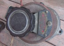
OK a few things. I am getting ready to put the other unit on the bench and test a few things. Mostly I want to compare the output transformer values with the first unit that I thought was not right. I am going to put my fluke on the variac and see if that works. I looked up the Hammond transformer that was in my 2010 parts express catalog and it is currently 112.04 much more than the 65.00 listing in the 2010 catalog. I think I am going to start out simple. Replace the can cap with 4 individual caps. leave the rectifier tube in and try bringing them up on the variac first just to see if they play. Seems like too much conflicting info out there and with me being a Tube Noob I can stick with what is safe and go from there. I can follow a schematic and build from there but I do not understand all that jargon. I have heard about bias but believe these amps do not have an adjustment and without some guidance I am just guessing at a lot of stuff. I will attach a few photos of my units
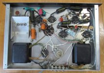
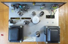
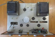
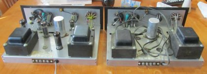
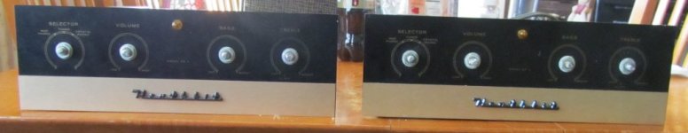
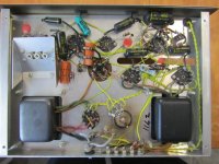
Just some photos of my stuff if anybody is interested. I believe they are both in pretty good condition. The unit I got from Ebay included original Box, Original instructions, original sales receipt 8 poster size diagrams of the wiring and parts and the unit looks mint as far as I can tell. Obviously I am no expert. Cost was 58.00 in 1959 and I paid 87.00 in 2013. The unit given to me for free has white wires for connections. the unit I got from Ebay has Yellow connecting wires. The 450v 33uf caps have arrived but they are still on my desk at work so that swap will have to wait for another day.
Attachments
- Status
- This old topic is closed. If you want to reopen this topic, contact a moderator using the "Report Post" button.
- Home
- Amplifiers
- Tubes / Valves
- New to Tube amps, heathkit question