Here are a couple of picss with the refurbished FET-10:
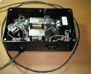
The new power supply is massive! It has a 200VA Torodial transformer, not to mention a lot of fileter caps. The difference rendered by the new power supply for the FET-10 is remarkable.
The sound from this setup is truly outstanding.
The new power supply is massive! It has a 200VA Torodial transformer, not to mention a lot of fileter caps. The difference rendered by the new power supply for the FET-10 is remarkable.
The sound from this setup is truly outstanding.
Attachments
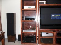
Actually, there are two PA-7's, and one PA-5 for the center channel. All the amps have been refurbished, and they sound great.
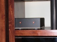
The new power supply for the FET-10 (it's the black box with the two LED's), makes a HUGE difference. It transforms the FET-10 to another level.
It almost seems that the original power supply for the FET-10 was designed by someone else. It really is pretty wimpy, and does not match the outstanding quality of the FET-10.
CD's from the Cambridge 840 are transformed with the upgraded FET-10.
Last edited:
The new power supply is massive! It has a 200VA Torodial transformer, not to mention a lot of fileter caps . . .
Can you say more about your new power supply? Is it just a big transformer plus diodes and big capacitors? If so, how much capacitance? Or is it a bit fancier?
Thanks,
---Gary
Hello Redwingnine,
Don't you plan to upgrade you shelf? With good managing vibrations, you can put your system on the top.
I wrote few lines about this:Managing vibrations, a straight way to enhance audio performances
Thanks again for your pictures.
I agree with you. I already done this kind of upgrade 20 years ago....The new power supply is massive! It has a 200VA Torodial transformer, not to mention a lot of fileter caps. The difference rendered by the new power supply for the FET-10 is remarkable. The sound from this setup is truly outstanding.
Don't you plan to upgrade you shelf? With good managing vibrations, you can put your system on the top.
I wrote few lines about this:Managing vibrations, a straight way to enhance audio performances
Thanks again for your pictures.
Hello Redwingnine,
I agree with you. I already done this kind of upgrade 20 years ago.
Don't you plan to upgrade you shelf? With good managing vibrations, you can put your system on the top.
I wrote few lines about this:Managing vibrations, a straight way to enhance audio performances
Thanks again for your pictures.
Eric, you're welcome.
Hadn't thought much about vibration management. I'll check it out and get back.
Gary, I'll pop the cover on the power supply later this week and post the pics. That should show most of what folks are after. I still can't get over what a diffference it makes with the FET-10. (The re-cap helped as well).
I recapped my FET-10/HL.
The outboard PS now has Nichicon FG power supply electrolytics (along with UF4007 diodes). Inside the main case, for the 4.7uF bypass, I used Elna Silmics.
Signal path - for the 1uF input capacitors, I replaced them with Relcap PPMFs which fit the same space perfectly. The 10uF output capacitors were a little more tricky - I ended up using 10uF/63V Wima metallized polycarbonates lying on their sides. It was a bit of a squeeze but everything works.
Subjectively speaking, the sound is a bit better - touch more detail, faster and more 'transparent'. I'm very happy and feel no need to buy anything else (for now!).
Attachments
I have the settings for the FET-10/PC - assuming they are the same:
As for setting up the impedance and capacitance loading - with the top open and the front of the preamplifier facing you, locate the two red 8 position dip switches on the far left side. If a dip switch is set to the left, it is ON. If it switched to the right, it is OFF.
Resistance Loading:
#1 - 22 ohms
#2 - 47 ohms
#3 - 100 ohms
#4 - 1,000 ohms
1-4 OFF = 47k ohms (ie, MM cartridge)
Capacitance Loading:
#5 - 1,000 picofards
#6 - 250 picofarads
#7 - 150 picofarads
#8 - 100 picofarads
5-8 OFF = 50 picofarads
To set the gain, locate the two jumper sliders on the middle left of the board. These are colored blue and each cover two pins of a three gold plated prong.
For highest gain, each jumper slide is positioned towards the center of the preamplifer. In this case the exposed pins are those nearest to the front and back of the preamplifier.
..... Does anybody know if there is any particular significance to this?
they must be of good quality , and more is better
even if difference between 1 and 10 isn't much significant
try biggest you can squeeze there
they must be of good quality , and more is better.
Ah yes, the mutually exclusive characteristics

I'm not particularly motivated to replace the 10 uF EPCOs in my unit, just curious about any interesting technical reason for the change. I assume it was an engineering change at Threshold.
new power supply
I built a new external power supply for my FET 10hl. The original power supply has a very puny transformer - only 6VA. I measured the current being drawn by the preamp and it draws about 3W steady state (it's a Class A preamp) so that's isn't much margin for the transformer. 6VA will deliver slightly less than 6W because there is some phase difference between current and voltage otherwise known as the power factor.
I upgraded the transformer to a 28VA transformer for extra headroom and changed from a traditional transformer - diode bridge - capacitor supply to a choke input supply, which consists of transformer - diode bridge - choke - capacitor supply. These are more commonly used in tube amps and are known to be very quiet. I also increased the size of the power supply caps to 2 x 10,000uf.
I wouldn't be writing if it wasn't a big improvement. Soundstage is huge and even more transparent than it was previously. Additionally a slight harshness/sibilance I was hearing, which I thought was due to my amplifiers has almost disappeared. It must be a good improvement because I keep wanting to listen to more music.
Attached is a schematic of the supply that I built. Not shown are the bypass caps that I used on the 10K electrolytics. I used Russian military caps - 10uf 63v (type K73-16) and 1uf 200v (type K40Y-9) and 0.22uf 630v (type K42Y-2).
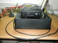
For scale I've attached a picture of the original supply sitting on top of the new one. The new one is quite a bit larger and heavier due to all the iron.
Happy listening.
---Gary
I built a new external power supply for my FET 10hl. The original power supply has a very puny transformer - only 6VA. I measured the current being drawn by the preamp and it draws about 3W steady state (it's a Class A preamp) so that's isn't much margin for the transformer. 6VA will deliver slightly less than 6W because there is some phase difference between current and voltage otherwise known as the power factor.
I upgraded the transformer to a 28VA transformer for extra headroom and changed from a traditional transformer - diode bridge - capacitor supply to a choke input supply, which consists of transformer - diode bridge - choke - capacitor supply. These are more commonly used in tube amps and are known to be very quiet. I also increased the size of the power supply caps to 2 x 10,000uf.
I wouldn't be writing if it wasn't a big improvement. Soundstage is huge and even more transparent than it was previously. Additionally a slight harshness/sibilance I was hearing, which I thought was due to my amplifiers has almost disappeared. It must be a good improvement because I keep wanting to listen to more music.
Attached is a schematic of the supply that I built. Not shown are the bypass caps that I used on the 10K electrolytics. I used Russian military caps - 10uf 63v (type K73-16) and 1uf 200v (type K40Y-9) and 0.22uf 630v (type K42Y-2).
For scale I've attached a picture of the original supply sitting on top of the new one. The new one is quite a bit larger and heavier due to all the iron.
Happy listening.
---Gary
Attachments
. . . I have a feeling that is worth trying that lower choke - moving to negative lower leg
Thanks for the suggestion. Can you say more about why it might make a difference? Each side of the supply is hooked up as a separate loop so I didn't think that it matters where the choke goes.
---Gary
say that ripple in upper neg leg and lower pos leg is same but in opposite phase ; you need them in same amplitude to superimpose them .
if you move lower choke to lowest leg , that way you'll also have same ripple in final pos and neg legs
difference maybe audible , maybe not .........
if you move lower choke to lowest leg , that way you'll also have same ripple in final pos and neg legs
difference maybe audible , maybe not .........
if you move lower choke to lowest leg , that way you'll also have same ripple in final pos and neg legs
I am reluctant to disagree with someone as esteemed as our own Zen Mod but I will in this case. I don't think that the ripple is changed by the location of the choke. If one says that the rectified AC from the bridge has a DC component Vdc and an AC component Vac, then it's simple to show that the capacitor charges to Vdc and the Vac term is attenuated by the ratio of Zc/(Zl+Zc) and the size and sign of the ripple is unaffected by the location of the choke. At least that's how it looks to me. But I'm happy to be corrected if I'm thinking about this in the wrong way.
Best regards,
---Gary
PS pictures
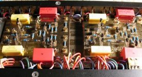
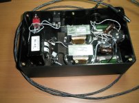
Here are a few photographs showing the construction of the power supply. I wired everything up by hand and did not use any circuit board. Many components are suspended by their leads from the terminals for the transformer or the capacitors. It looks a bit messy but this type of construction sounds very good since everything is isolated in free space with minimal coupling.
Here are a few photographs showing the construction of the power supply. I wired everything up by hand and did not use any circuit board. Many components are suspended by their leads from the terminals for the transformer or the capacitors. It looks a bit messy but this type of construction sounds very good since everything is isolated in free space with minimal coupling.
Attachments
GaryB - you have all rights to dissagree with anyone , especially with someone so not-serious as ZM is 
my thoughts aren't directed on electrical function of circuit itself ( and mea culpa for not addressing that) but more on physical layout of circuit itself ;
meaning that -for best results- physical layout of adjacent routes in PSU must be symmetrical/identical too .....
maybe splitting a hair but - in this hobby we are used to look at that last one ( hair )
)
all in all - kudos for passion and approach

my thoughts aren't directed on electrical function of circuit itself ( and mea culpa for not addressing that) but more on physical layout of circuit itself ;
meaning that -for best results- physical layout of adjacent routes in PSU must be symmetrical/identical too .....
maybe splitting a hair but - in this hobby we are used to look at that last one ( hair
)all in all - kudos for passion and approach
- Status
- This old topic is closed. If you want to reopen this topic, contact a moderator using the "Report Post" button.
- Home
- Amplifiers
- Pass Labs
- New (to me) Threshold FET-10 HL (What to refurbish?)