A scope is essential tbh... and I think ostripper agrees that the CFP output isn't suited to this style of construction. It needs supreme care in layout, preferably on a correctly designed PCB.
When I think back 30 odd years to when I started playing around with designs like this, they were fraught with stability issues... and a 'scope showed all the problems. Even bringing your hand near the outputs, or connecting a probe and the things would burst into oscillation. At the time I just didn't appreciate all the subtleties... that a couple of inches of wire to a driver or output device can turn it into an oscillator due to the wire being inductive, and a hundred other ways for it to occur too.
30 years later, after spending all that time working in electronics I know why these problems occured... and your going over the same ground.
The original EF variant of the blameless amp is workable on stripboard with care... it doesn't need any additional caps for stability.
could any of this be due to my choice of transistors? I picked some small signal kas992 where the hfe dropped off after about 5ma, and the Cob is about 2pf. I also though that those might not be sufficient for the vas, I was worried about the flat range of hfe, so I got some other medium current ones, hfe flat to 50ma, Cob 40pf though... Both have Ft greater than 50mhz.
My question being, does hfe need to be flat or linear in the range of use for this application, I.e. Should I just try to use the small ones for the vas even though hfe starts to fall around the current that I'm using for the vas? The gain is around 400-600 and I thought that the gain of the EF vas would then have ridiculous gain and thus be limited by degeneration? So maybe the nonlinear hfe wouldn't matter so much, so long as it's still really high?
My question being, does hfe need to be flat or linear in the range of use for this application, I.e. Should I just try to use the small ones for the vas even though hfe starts to fall around the current that I'm using for the vas? The gain is around 400-600 and I thought that the gain of the EF vas would then have ridiculous gain and thus be limited by degeneration? So maybe the nonlinear hfe wouldn't matter so much, so long as it's still really high?
Last edited:
The blameless amp is very tolerant of devices used. It would work with pretty much anything of suitable rating.
I don't recognise the KAS992.
The original types are 2n5551 and 2n5401 for small signal stuff and MJE340 and 350 for drivers. Typical hfe for the 2n's would be around 150 and around 40 at a guess for the MJE's
You are looking to deep into it at the moment")
I don't recognise the KAS992.
The original types are 2n5551 and 2n5401 for small signal stuff and MJE340 and 350 for drivers. Typical hfe for the 2n's would be around 150 and around 40 at a guess for the MJE's
You are looking to deep into it at the moment
ksa992 or maybe ksc? I don't remember. I was just worried that my vas transistor has a cob of 40pf and the cdom is only 100... Don't know enough to say if that's bad, but it seems bad. The cdom is supposed to 'swamp' the miller capacitance isn't it? Anyway I'm just gonna build the next one and see what happens.
Thanks again guys! If I ever get an oscope I'll try to post some findings.
Thanks again guys! If I ever get an oscope I'll try to post some findings.
Hmmm it's a 2SA probably
http://www.datasheetcatalog.org/datasheet/nec/2SA992.pdf
It is very high gain under certain conditions, you are right, and only 50ma Ic rating. The 2N5551 etc are 600ma devices. 50ma is too low for the VAS really.
The gain in itself shouldn't make much difference... that's the beauty of good circuit design, but could it with a layout problem... I wouldn't like to say.
When Dougs design appeared 15 or more years back I did breadboard it properly to evaluate before building on PCB's and it was fully stable.
a VAS duty transistor will have:
good gain, hFE>100 and preferably >150
good speed, fT>100MHz and preferably >200MHz.
good linearity over a range that includes operating bias.
good speed over a range that includes operating bias.
low capacitance, Cob<10pF and preferably <4pF
sufficient Vce to exceed the supply rails.
Ic sufficient for peak loads before serious gain droop interferes with performance. Ic max >50mA and preferably >100mA.
sufficient power dissipation for the combination of Ibias & Vrail, P>3W and preferably >7W and more than 4times Pq.
Look at 2sa1360 and 2sa1407 as excellent VAS duty transistors.
does anyone have a list of these kinds of useful transistors? It was hard for me to find the ones I got and I really just bought them based on a few parameters that I thought were as good as I was gonna get. But seeing that transistor I was obviously wrong about being as good as I could get.
Sorry I wasn't home before, but all the transistors were written in the first post. ksa916yta is the bigger one, ksa992fta is the smaller one.
http://www.fairchildsemi.com/ds/KS/KSA992.pdf
http://www.classiccmp.org/rtellason/transdata/ksa916.pdf
http://www.fairchildsemi.com/ds/KS/KSA992.pdf
http://www.classiccmp.org/rtellason/transdata/ksa916.pdf
Don't get hung up on exotic devices... at least not at this stage.
You can find most original data sheets here,
Datasheet catalog for integrated circuits, diodes, triacs, and other semiconductors, view
As mentioned, 2N5551 and 2N5401, also MPSA56 and MPSA06, and BC546 and BC556 are typical of general purpose small signal devices... good for 99% of applications.
BD131 and BD132, BD139, BD140, MJE340, MJE350 for medium power devices.
There are countless similar suitable devices.
Ok so i just noticed that I'm also getting DC offset, Its not in the signal before the filter, but at the input gate i get about 80mV of dc offset at the input line, Since the high pass filter is on the NFB it doesn't get amplified but its obvious in the output to the base drivers, ones 650mv and the other 450mv.
Do you know what could be causing this offset? I checked the power supplies and hooked up two higher powered, more filtered ones and its still there. They read + and - 27.1 And that's the best my multimeter will give me.
I think I am going to goto the EF circuit. Ive been testing all night with the CFP circuit changing caps trying to find the smallest stable values and when I hooked up the switching power supplies that I'm going to be using for the final circuit the circuit goes quiet sometimes. I.E. there will be input but no output. Eventually the circuit will kill the input device, basically suck a bunch of juice from it and overheat it (a cheap usb audio thing) and I'll have to restart it. But for some reason when I plug the jack back in I get some contact noise and that seems to "jumpstart" the circuit from quiet mode...
This fun little phenomenon hasn't happened with the low power supplies since I soldered it up, but it did on the breadboard before more often than not. So I'm guessing its some sort of oscillation that I can't hear. Which lead me think that the 40khz switching might be ******* it off, and I put the inrush resistors in before the main caps (so they would act like a low pass filter) and it started up fine.
Boy there's just a bunch of crap to worry about. Now i've got to figure out how to get the EF circuit thermally compensated if I want to go that way. I've seen someone run some wires from the Bias transistor and attach it to the top of the output transistor that way, but I bet that's a no-no right? Seems like I really need a prototyped board, maybe I should sit down and learn EAGLE or something?
input offset current causes a voltage drop across the Rin resistor.
If the same current passes the same value of feedback resistor, then the input offset voltage at the two inputs (+IN, -IN) will be exactly equal. The output of the differential pair (LTP) should now be zero since it should be designed and built to amplify differences.
If both the +IN & -IN are equal in value then the output offset should be near zero. Minor trimming of VAS current could be used in conjunction with a well matched LTP to have near zero output offset.
You are worrying to much about the all the fine detail and overlooking the main problem... your layout
If the thing isn't oscillating (unstable) then the main check is the DC offset at the output, and it should be within 100mv for unselected (non matched) transistors.
DC voltage on the base of the input devices is correct... it won't and can not be zero due to the bias current flowing out of the PN junction.
Thermal coupling of vbe generator with EF outputs, post number #18
http://www.diyaudio.com/forums/soli...t-top-body-output-transistor.html#post1429206
So on top of the output is one way to do it.
http://www.diyaudio.com/forums/soli...t-top-body-output-transistor.html#post1429206
So on top of the output is one way to do it.
Yea ok, I realize that the layout kinda janko right now. Tomorrow hopefully I'll have time after work to get some components on a new board where everything is on the board as i had posted before. Since I didn't get any objections, it must not be so bad then...
I tried just swapping the CFP with an EF output (Flipping it upside down and swapping drivers) also shortened the driver wires a bit and I cant get it to sound nearly as good as I did with the CFP, its also got a lot more background noise, and it was making weird sweeping noises for a while. I thought I was being attacked by aliens. Hopefully it works on a board better. Thanks again guys.
I tried just swapping the CFP with an EF output (Flipping it upside down and swapping drivers) also shortened the driver wires a bit and I cant get it to sound nearly as good as I did with the CFP, its also got a lot more background noise, and it was making weird sweeping noises for a while. I thought I was being attacked by aliens.
Hopefully it works on a board better. Thanks again guys.thanks again mooly I figured as much.
Also, andrew thanks for that explination, I guess that means that I shouldn't have the input highpass pulldown resistor much different than the main feedback resistor? I think I might remember that now from the online guide, oops.
Also, andrew thanks for that explination, I guess that means that I shouldn't have the input highpass pulldown resistor much different than the main feedback resistor? I think I might remember that now from the online guide, oops.
Last edited:
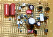
Ok so here's what I got so far. I haven't soldered much yet it's just placed/jammed in there. Input goes top left and middle left with a jumper to the center ground. I haven't made the jumper from the input to the base of the transistor yet, so you can see its just chillin' there.
Everything is 1/4W resistors, the small transistors are ksa992fta and complements while the drivers and vas are ksa916yta and complements. I thought those seemed to be appropriate sizes from my limited choices. I also have some MJE172/182 but I thought they might be a bit much for drivers and their a little low on the voltage, I bought them when I didn't know what I was gonna do yet. My final plan is +-60 rails.
Outputs on the right, I plan to have a set of stubby wires from the drivers to the output transistors (like I have seen here before) or maybe just bend the leads, leave them long enough and solder them on the edge.
The output resistors will end up hanging off the heat sink as well, which means an NFB wire will need to run back to the center of the circuit. This will then be the only 'wire' of any length apart from the input wires coming in.
There are no jumps on the back, although in some places it might make sense to move them back there.
Please tell me if the setup looks acceptable enough to think that its gonna work out.
Attachments
It's scary stuff
Is it gonna work ? honest answer... anythings possible... but there's lot's of problems.
The drivers !! A 2SA916. That's a 50 milliamp device, they just won't survive as the volumes turned up. I don't think you realise how much current an amp can draw under full load.
and -/+60 volts, that's way to ambitious for anything built like this.
Cobbling something together with inappropriate parts is just asking for trouble.
I can't do all the work for you, so my advice would be to try something much less ambitious such as a Gainclone kit... you would learn a lot and hopefully end up with a working amp.
If you are intent on building Dougs amp use the correct components, a modest PSU of no more then -/+25 to 30 volts to start, and use a LARGE as in say 6 by 4 inch piece of strip board for the amp and lay it all out following the circuit as a rough layout guide. Use proper drivers with heatsinks... and build the EF version.
ksa916 is 800ma, 900mw... Am I missing something? They are not 2sa, I don't know where you keep getting that label from. The datasheet is on page 3, I linked to it.
sorry if I'm coming off demanding, but you see the goal for me is not to have a working amp. It's to suck out all the knowledge I can about amp design.
you keep saying that the layout is the reason for a lot of my troubles so I figured I'd come up with a new layout and post it so people could say, oh that's stupid the vas should be closer to the drivers, or you shouldn't put transistors close to caps or something.
I've said it many times, the first amp I built worked after I added the driver caps, I'm really just trying to find out the best way to go about improving on dougs design by simply using componets that aren't older than dirt. Sorry if my intentions were not clear.
But as always thanks for the advice mooly, you've been a real asset.
Last edited:
My mistake with the transistor... sorry... comes from years working with JIS markings.
Your amp "worked" after adding caps because you were killing the HF response such that the amp couldn't oscillate, but that would impact severely on the performance and distortion if you actually measured it.
You can stop a purpose designed oscillator by doing that
Dougs design doesn't need exotic components... it can be built with stuff that was around in the 1970's and 80's... honest. And meet it's full specification.
The last thing I want to do is discourage you, so I guess your going to have to go ahead and build it... and see where that takes you.
- Status
- This old topic is closed. If you want to reopen this topic, contact a moderator using the "Report Post" button.
- Home
- Amplifiers
- Solid State
- New to DIYAudio Help With New Build?