I have read several posts in this thread about the use of high temperature solder for the power tube bases. Could somebody tell me please what melting point is required for this. Thanks.
We use ordinary solder, lead free, it has a melting point of 217C, we never had a problem with that. The reason why we use lead free is just because of RoHS requirement, otherwise we would probably use ordinary lead based solder as it is easier to use.
There are many tales of socket problems for 6C33C but in my opinion most of what has been written is based on lack of basic knowledge in electronics, hint: contact pressure is often more important than contact area for high current connectors.
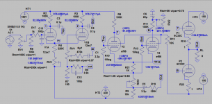
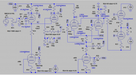
In this version you can adjust the sweet spot of 12ax7 LPT stage with just one control. It sounds very good and sweet when LTP1 approaches zero bias in my amp.
Have you tried ccs using 2sk117 as mine ? Now I shall swich the ccs to penthode. I expect more sweet sound and less noise.
Attachments

Have you tried ccs using 2sk117 as mine ? Now I shall swich the ccs to penthode. I expect more sweet sound and less noise.
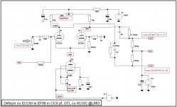
Not yet, yes soon I can replace 68k resistor hooked to -140V with 2sk117 not a big problem , but if pentode I need another eyelet board as I need to add another tube socket. Can complete in one day when I finalise the drawings. How you make yours?
Not yet, yes soon I can replace 68k resistor hooked to -140V with 2sk117 not a big problem , but if pentode I need another eyelet board as I need to add another tube socket. Can complete in one day when I finalise the drawings. How you make yours?
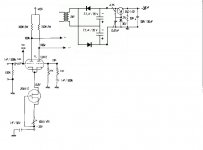
2sk117 replaced the 470K resistor and neon lamp, has it's own PSU -35V and drain liked to the cursor of RV1 (1k)
You are right to be little difficult with EF86 ccs as I need also separated filament supply as well as wiering and socket, but I think it worth.
I see all these changes and have to ask. Are they making the original design better or just going if a slightly different direction? I have one more build to finish then will start on this amp is why I am asking. Cheers, Dennis.
You will need 2 amps or 2 channels in order to compare the sonic, so you should start one channel original and then 2nd channel with changes you expect it will make a difference such as independence -430V for LTP, because original is riding on top of psu of output stage which will cause too much fluctuation for direct coupling..and add in changes one by one slowly.
I see all these changes and have to ask. Are they making the original design better or just going if a slightly different direction? I have one more build to finish then will start on this amp is why I am asking. Cheers, Dennis.
This is our contribution to Tim's project let say.
My advice is to compleat Tim's design as it was first publishet, I am confident and you shall be satisfied. Then, after several month of listening and enjoy, you can add some details as we did. Good luck
I think a different means of balancing needs to be used. The current system of a balance pot in the cathodes of the differential input is a bad place to do it- differential amps work best if the cathodes are tied directly together!
A two-stage CCS should also be employed. If a single stage, the differential amp will leave performance on the table.
A two-stage CCS should also be employed. If a single stage, the differential amp will leave performance on the table.
Thanks Guys. I'll start with the original as suggested. I will start working on the chassis in a couple weeks. I have all the big stuff: transformers, tubes, sockets, big caps and such. Now I just need the do-dads.
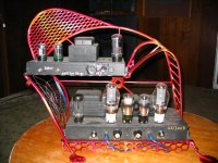
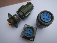
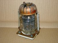
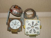
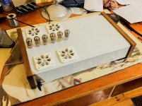
Here is a pic of my chassis stand. I sold the 300B amp so disregard that. The bottom chassis will hold the power supply and the top chassis will hold the tubes. They will be connected by old military screw connectors like the one shown.
I made the chassis already out of plate bronze but I need to make the corner supports out of brass plate and drill all the holes.
all 4 tubes will stand out in front of the top chassis. I have 2 of the sockets shown but can't find any more of them although I've been looking for 5 years now. So I'll rise the 2 middle tubes up by a 1.5" Purple Heart riser and the 2 sockets in the pix will flank them like guards.
It should look good.
Attachments
Last edited:
I think a different means of balancing needs to be used. The current system of a balance pot in the cathodes of the differential input is a bad place to do it- differential amps work best if the cathodes are tied directly together!
A two-stage CCS should also be employed. If a single stage, the differential amp will leave performance on the table.
Thank you very much! Maybe we can do something like this.
Attachments
Last edited:
Thanks Guys. I'll start with the original as suggested. I will start working on the chassis in a couple weeks. I have all the big stuff: transformers, tubes, sockets, big caps and such. Now I just need the do-dads.
djn, I'm about to start my own Tim Mellows OTL. I am expecting most of the large parts tomorrow. I too will build the amp as designed by Tim first and then experiment.
I think a different means of balancing needs to be used. The current system of a balance pot in the cathodes of the differential input is a bad place to do it- differential amps work best if the cathodes are tied directly together!
A two-stage CCS should also be employed. If a single stage, the differential amp will leave performance on the table.
Do you mean something like this:
Attachments
Do you mean something like this:
Not yet, I am finishing the 2sk117 ccs, then I'll pass to penthode.
Thanks Guys. I'll start with the original as suggested. I will start working on the chassis in a couple weeks. I have all the big stuff: transformers, tubes, sockets, big caps and such. Now I just need the do-dads.
Here is a pic of my chassis stand. I sold the 300B amp so disregard that. The bottom chassis will hold the power supply and the top chassis will hold the tubes. They will be connected by old military screw connectors like the one shown.
I made the chassis already out of plate bronze but I need to make the corner supports out of brass plate and drill all the holes.
all 4 tubes will stand out in front of the top chassis. I have 2 of the sockets shown but can't find any more of them although I've been looking for 5 years now. So I'll rise the 2 middle tubes up by a 1.5" Purple Heart riser and the 2 sockets in the pix will flank them like guards.
It should look good.
Nice amp stand, with 6c33c sockets and cap's shall be true Art-nouveau, BRAVO! I like it.
Could someone please advise me if it is necessary to use fiber washers up against the tube bases to take into account the expansion when they get hot. None of the fiber washers that I have looked at will tolerate any greater than 100° C, so maybe it isn't an option anyway.
I wouldn't think so G. Ceramics don't expand and contract nearly as much as metals do. I've seen many many many amps without them. You should be fine.
I like that chassis. What side is going to be the front? I like to see tubes standing front and center just cuz they look cool.
I like that chassis. What side is going to be the front? I like to see tubes standing front and center just cuz they look cool.
- Home
- Amplifiers
- Tubes / Valves
- New Tim Mellows OTL project