That was all pretty old. This thread was the most up to date descriptions for builds.
That's incredibly old. I have the current schematics, for anybody who wants 'em.
P
Not that I want to do do archeological digs, but is there anyone with the ‘current’ schematics referred in the quote? The email audiotropic at gmail dot com seems dead... unfortunately.
Thank you!
ziffel,
I hate spell checkers!
it wanted to change your moniker from ziffel to Eiffel.
Good question!
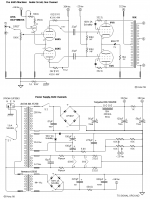
The schematic, Post # 127, has 322V B+, the primary DCR will cause slightly less voltage at the plate and screen. The tubes are in Triode Mode.
The amp uses adjustable fixed bias, not self bias.
With 1V across the 15 Ohm common cathode sense resistor, the total current is 66mA, and
Is 33mA per output tube.
315V x 0.33A = 10.5 Watt dissipation
Caution: do not modify this amp to operate 6W6 tubes in Beam Power mode, because . . .
Too high of a screen voltage, too much dissipation.
Your mileage from the fire department may vary.
6W6 6V6
330V max (Plate) 350V max (Plate)
330V max (Screen, Triode Mode) 315V max (Screen, Triode Mode)
165V max (Screen in Beam Power mode)
8.5 Watt max diss. (Triode Mode) 10 Watts diss. (Triode Mode)
Filament 6.3V 1.2A Filament 6.3V 0.45A
Watch out here . . . Nice low current
Lots more current
Required
from the power
Transformer
Each cathode should return to ground through its own individual 30 Ohm resistor
(take out that 15 Ohm common cathode resistor).
That way, you can adjust each tube cathode current individually, 1V = 33mA.
The output transformer will give better performance (it needs a very well balanced DC current, it is a push pull transformer). Current that is not balanced causes early saturation and poorer low frequency performance.
the push pull transformer is Not an air gapped single ended transformer.
And . . . you can adjust the bias to less than 33mA to keep the dissipation at 8 Watts, or 10 Watts as needed by the tube (6W6 and 6L6 respectively).
Or, you can drop the B+ voltage slightly by using a resistor in series with the choke.
The input stage takes 3.5 to 5 mA. The output stage takes 66mA. A 100 Ohm resistor at 71mA drops 7 V, a 200 Ohm resistor drops 14V.
You multiply the B+ volts x 33 mA, and get the dissipation. Keep it no more than 8 Watts and 10 Watts for the 6W6 and 6L6 respectively.
Go for good sound, but also go for reliability too.
I hope that helps.
Happy building, happy listening.
Let us know how those 6W6 work and sound in that amp.
I hate spell checkers!
it wanted to change your moniker from ziffel to Eiffel.
Good question!
The schematic, Post # 127, has 322V B+, the primary DCR will cause slightly less voltage at the plate and screen. The tubes are in Triode Mode.
The amp uses adjustable fixed bias, not self bias.
With 1V across the 15 Ohm common cathode sense resistor, the total current is 66mA, and
Is 33mA per output tube.
315V x 0.33A = 10.5 Watt dissipation
Caution: do not modify this amp to operate 6W6 tubes in Beam Power mode, because . . .
Too high of a screen voltage, too much dissipation.
Your mileage from the fire department may vary.
6W6 6V6
330V max (Plate) 350V max (Plate)
330V max (Screen, Triode Mode) 315V max (Screen, Triode Mode)
165V max (Screen in Beam Power mode)
8.5 Watt max diss. (Triode Mode) 10 Watts diss. (Triode Mode)
Filament 6.3V 1.2A Filament 6.3V 0.45A
Watch out here . . . Nice low current
Lots more current
Required
from the power
Transformer
Each cathode should return to ground through its own individual 30 Ohm resistor
(take out that 15 Ohm common cathode resistor).
That way, you can adjust each tube cathode current individually, 1V = 33mA.
The output transformer will give better performance (it needs a very well balanced DC current, it is a push pull transformer). Current that is not balanced causes early saturation and poorer low frequency performance.
the push pull transformer is Not an air gapped single ended transformer.
And . . . you can adjust the bias to less than 33mA to keep the dissipation at 8 Watts, or 10 Watts as needed by the tube (6W6 and 6L6 respectively).
Or, you can drop the B+ voltage slightly by using a resistor in series with the choke.
The input stage takes 3.5 to 5 mA. The output stage takes 66mA. A 100 Ohm resistor at 71mA drops 7 V, a 200 Ohm resistor drops 14V.
You multiply the B+ volts x 33 mA, and get the dissipation. Keep it no more than 8 Watts and 10 Watts for the 6W6 and 6L6 respectively.
Go for good sound, but also go for reliability too.
I hope that helps.
Happy building, happy listening.
Let us know how those 6W6 work and sound in that amp.
Last edited:
Thank you, 6A3sUMMER. You are always so helpful. I am very grateful for it.
I have the output transformers. I am about to buy power transformers from Antek and Allied chokes from Newark. I need to make an amp to stay sane during this plague. The lock down has reduced my income so this has to be a super cheap build.
Thank you again and best wishes - az
I have the output transformers. I am about to buy power transformers from Antek and Allied chokes from Newark. I need to make an amp to stay sane during this plague. The lock down has reduced my income so this has to be a super cheap build.
Thank you again and best wishes - az
baudouin0,
I suggest that everyone take those diodes out, except for certain RF amplifiers.
Post # 19 of "Questions About This Local NFB Scheme" has this to say:
A Partial quote from post # 7 (6A3Summer):
I have tried multiple times to get someone on these threads and this forum to give a real, proper, and formal proof, as to why those diodes are needed. Nobody has responded with a formal proof (at least I have never seen one). Therefore, I declare that the reason for the diodes is "An Old Wives Tale".
The actual origin of the screen grid diode was an old Eimac application note for a RF transmitting TETRODE where under certain conditions the the screen grid could experience a negative resistance region and emit electrons, causing spurious oscillation (illegal in a radio transmitter).
Tubelab_com answers:
The diode prevents this. This is rarely seen in any tetrode, and usually only seen in small geometry RF tetrodes where the screen is at a far lower voltage than the plate. I have seen this happen in a screen driven pentode amp where overdrive can make the grid red hot, then it will emit electrons that travel to the plate causing a tube arc. I put a diode in series with the screen grid to prevent this. This should NEVER happen in a normal G1 driven pentode, therefore the diode is unnecessary, and can cause distortion under some conditions.
Then an "old wife" created a tale that garnered a following about 15 years ago. Once a "guru" gets a "truth" it can propagate forever. Anyone remember the "Optimized Electron Stream Technology?" I tried it, got a blown EL34 for my effort. If one wants to read a long winded BS story, one can dig as deep into the substance as one can stand here:
Tubes
The magic diodes begin to appear about a third of the way down the page, magic chokes come later. Both get more mention elsewhere on the web site if I remember right. I haven't looked in at least 10 years.
Last edited:
I suggest that everyone take those diodes out, except for certain RF amplifiers.
Post # 19 of "Questions About This Local NFB Scheme" has this to say:
I would be disappointed if we summarily dismiss those diodes between the plates and the screens, without further discussion of the topic or proof of their folly (apologies if it had already been discussed elsewhere; in that cast a link will be appreciated.)
Poinz designed and incrementally improved the “Musical Machine” over many years, while being very critical about each part, and synergism between parts. I don’t know for sure but I doubt that he added those diodes without critically listening. I believe many Musical Machines were built over the years and I have seen plenty of accolades, but never read complaints about performance or issues with those diodes. I would like to hear from folks who built this amp and tried it with AND without the diodes. What did you hear?
Please take a look at this material and tell us what you think of it.
Pentodes & Tedrodes to Triodes
Looks plausible to me, but I’m no electrical engineer. I know that Bruce Rozenblit (Transcendent Sound) used this “voltage shifter” in some of his amps, apparently successfully. The diodes that Poinz designed into the Musical Machine is essentially the same circuit minus the voltage shifting zeners and associated capacitors an resistors.
Francois G,
We are not summarily dismissing anything.
Look again at Post # 19.
Do not look at what I said there, instead look at what Tubelab_com said.
A Major Manufacturer of RF tubes, Eimac, wrote an application note about using the diodes on the screens of RF Power Tetrodes.
The screens of RF Power Tetrodes can exhibit Negative Resistance.
And some screens of non-RF Power Tetrodes can exhibit Negative Resistance too.
The key word is "Tetrode", True Tetrodes.
Filament/Cathode, g1, g2, Plate. 4 elements (Tetra)
Multi grid Audio tubes are mostly Pentodes and Beam Power tubes.
Pentodes: EL84, EL34
Beam Power: 6L6, KT66, KT77, KT88, KT120, KT150, 7591, 8417, 807, etc.
Audio Beam Power tubes are often referred to as Beam Tetrodes.
But they are not real Tetrodes.
Audio Beam Power tubes have Beam Formers "g"3. (5 elements, not 4 elements).
True Tetrodes do not have Beam Formers (an extra element).
There is also some confusion with nomenclature, because some True RF Tetrodes are also called Beam Power tubes. But they do not have a Beam Former element.
Instead, the control grid and the screen grid are built like bird cages, with exactly the same number of vertical wires, and they line up. The cathode can see the plate directly through the 2 "bird cages". This causes the electron stream to "Beam", and that is the reason they call it an RF Beam Power tube.
If you want to see a True RF Tetrode, (that is also called a Beam Power tube), there are many.
4-65A (I built an audio amplifier with 4-65A once), 4-125A, 4-250, 4-1000A, 4X150A, etc.
There are no suppressor grids, and no Beam Former element (no g3).
And then, there are RF True Beam Power tubes. They have Beam Formers, not suppressor grids.
Examples are the 813, and 5894. 5 elements.
I suspect the 829B and 832A also have Beam Formers. 5 elements
I doubt that g3 on these tubes is a suppressor grid.
As to the link you posted, the purpose of the many Zener diodes is to drop the screen voltage far below the plate voltage, when the tube is used in
Triode Wired mode.
I would argue that this threads musical machine that uses a single common diode will only drop the screen voltage by about 0.6V.
And that is not a Triode wired circuit.
Dropping a screen voltage by 0.6V is not likely to change the operating conditions of the tube by enough to notice a difference.
My mains power varies from 117VAC to 123VAC. With a 3x (6X full secondary), that will change the B+ by 18V, far more than a single 0.6V diode.
Yes, there may be some reason to use diodes on the screens of Audio Pentodes and
Audio Beam Power tubes.
But I expect it is for when the tubes are used in special modes and extreme conditions that might cause the need for such diodes.
I would question anything that turns on and off the screen. Does that cause a click, a transient, etc.?
I am afraid that if you want to see the original Eimac application note about diodes and Tetrode screens, you will have to do the research yourself.
Last edited:
Francois G,
Quiescent maximum specs:
An 807 screen is rated for 300V maximum.
Unless . . .
You tie the screen to the plate (100 Ohm suggested), then the screen is "suddenly" rated for 400V maximum.
Consider in Beam Power mode, the screen is at 300V, the plate is at 600V.
When g1 goes to zero, the plate goes to perhaps 50V, and the screen is still at 300V.
The screen draws very large current, and that high current times 300V heats the screen.
Consider in Triode wired mode, the screen is at 400V, and the plate is at 400V.
When g1 goes to zero, the plate goes to perhaps 50V, and the screen also goes to 50V.
The screen draws a little more than normal current, and that times 50V hardly heats the screen.
Now, if you really wanted to use the 807 plate at 600V in Triode wired mode, you have to
use 200V of Zener diodes for the screen, to get the quiescent screen voltage at 400V.
But that will not actually work, because long before the plate goes to 50V, the screen will have Zero volts. The plate at 200V, will put the screen at Zero volts.
It did not gain much of anything over just putting the plate and screen at 400V, and throwing out the Zeners.
Now you see why I am not a fan of using the Zener(s) in Triode Wired mode.
Just my opinion.
Last edited:
baudouin0,
I suggest that everyone take those diodes out, except for certain RF amplifiers.
Post # 19 of "Questions About This Local NFB Scheme" has this to say:
A Partial quote from post # 7 (6A3Summer):
I have tried multiple times to get someone on these threads and this forum to give a real, proper, and formal proof, as to why those diodes are needed. Nobody has responded with a formal proof (at least I have never seen one).
"Real, proper, and formal proof" is what you encounter in maths. Nowhere else.
Therefore, I declare that the reason for the diodes is "An Old Wives Tale".
The actual origin of the screen grid diode was an old Eimac application note for a RF transmitting TETRODE where under certain conditions the the screen grid could experience a negative resistance region and emit electrons, causing spurious oscillation (illegal in a radio transmitter).
Some power pents will do this. I encountered the problem when working up a design that used 807 finals running in pentode mode. The solution is screen stoppers, 1K5 carbon comp resistors fixed the tendency to make these "snivets". Some spec sheets will recommend screen stoppers or some positive fixed bias for suppressor grids/beam formers that bring these connections outside (802, 803). As for the 6V6/6AQ5, no mention of snivet troubles with these types. Of course, including screen stoppers doesn't hurt even if they're not strictly necessary.
As for real tetrodes (no suppressor, no beam formers) these types always have some nasty "kinks" to their characteristic that means negative resistance and ESSSSSSS-loads of audio distortion. There were some designs that exploited this negative resistance characteristic to make negative resistance oscillators.
As for the series diodes in the schemo of post #6, I don't see any benefit nor detriment. Put 'em in or leave 'em out: your preference.
- Status
- This old topic is closed. If you want to reopen this topic, contact a moderator using the "Report Post" button.
- Home
- Amplifiers
- Tubes / Valves
- New project; Musical Machine