Any development on your project? i'm interested on this and planning to build if succesfull...
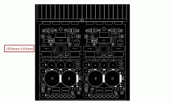
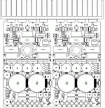
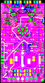
Well, I'm doing PCB.
I will show the next pictures soon
You interested this project,you will have a PCB if you want.
Regards,
After I assembled (point to point,not yet PCB complete) with this circuit it is not good.
Bandwidth is limited(-2db at 20khz,-5db at 40khz with load 4 ohm/20W # 12.6Vpp)
Reason is not enough current to driver MOSFET at high frequency + not negative feedback.
Because input capacitance of the lateral mosfet about 600pF
At frequency 40khz input impedance of Lmosfet only 665 ohm # 36mA input current for two lateral mosfet.
Tube have not enough current to driver(Ia max #13.5mA).
So I decided add a driver stage using mosfet (to increase the input impedance).
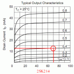
I choose driver 2SK214+2SJ77(160V,500mA,30W) of Hitachi (renesas),very easy to buy.
After I change,it had better(-0.5db at 20khz,-1db at 40khz,-2.5db at 70khz with load 4 ohm/20W # 12.6Vpp)
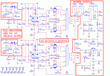
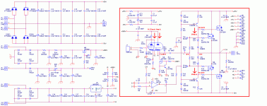
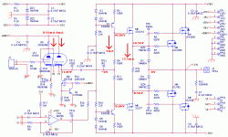
The change circuit for this project.
Bandwidth is limited(-2db at 20khz,-5db at 40khz with load 4 ohm/20W # 12.6Vpp)
Reason is not enough current to driver MOSFET at high frequency + not negative feedback.
Because input capacitance of the lateral mosfet about 600pF
At frequency 40khz input impedance of Lmosfet only 665 ohm # 36mA input current for two lateral mosfet.
Tube have not enough current to driver(Ia max #13.5mA).
So I decided add a driver stage using mosfet (to increase the input impedance).
I choose driver 2SK214+2SJ77(160V,500mA,30W) of Hitachi (renesas),very easy to buy.
After I change,it had better(-0.5db at 20khz,-1db at 40khz,-2.5db at 70khz with load 4 ohm/20W # 12.6Vpp)

The change circuit for this project.
Attachments
Last edited:
gate stoppers are too high.
I use 330ohm or 220ohm in similar circuit. No oscillation.
gate resistor + Ciss is a low-pass filter.
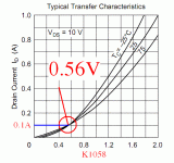
Ciss of 2SK1058 is 600pF,Rg=820R
Ciss of 2SJ162 is 900pF,Rg=470R
Fcut # 2Mhz( lost 3db)
Regards,
Last edited:
In last the post,i miscalculation, Fcut # 320khz. If you choose 300R=> Fcut >450khz
In the circuit NFB or circuit lager bandwidth very easy to oscillation.I choose gate resistors is 820R/470R also for this reason and it not affect the bandwidth of the sound(20-20khz)
In the document you share.I do not know why Ciss of P chanel(900pF) larger Ciss of N chanel(600pF),but gate resistor of P chanel(240-330R) is larger gate resistor N chanel(190-210R)?
Attachments
Yes,it is not much affected to the extent can be distinguished by ear but the measuring may be realize the difference.
Some carefully designs they use one driver for one mosfet.Although the theory is not necessary because Ig is too small(at high frequency Igmax is tens of mA),while each driver can provide hundreds of mA?
Some designs they trying to reduce harmonic distortion as low as possible,but many other design they trying to increase the harmonic distortion.
For me,I'd harmony between technology and art in my design
Some carefully designs they use one driver for one mosfet.Although the theory is not necessary because Ig is too small(at high frequency Igmax is tens of mA),while each driver can provide hundreds of mA?

Some designs they trying to reduce harmonic distortion as low as possible,but many other design they trying to increase the harmonic distortion.
For me,I'd harmony between technology and art in my design
1200pF (two pairs) are about 7kohm @20kHz...not really bad for a tube buffer direct drive 
1800pF is 4,5kohm @20kHz
Swap the triode and the pentode. Use the pentode for drive the FETs, and triode section for voltage-amplifier.
Triode mu is 40, so you can easy obtain 20-25gain with classic common-cathode.
1800pF is 4,5kohm @20kHz
Swap the triode and the pentode. Use the pentode for drive the FETs, and triode section for voltage-amplifier.
Triode mu is 40, so you can easy obtain 20-25gain with classic common-cathode.
1200pF (two pairs) are about 7kohm @20kHz...not really bad for a tube buffer direct drive
1800pF is 4,5kohm @20kHz
Swap the triode and the pentode. Use the pentode for drive the FETs, and triode section for voltage-amplifier.
Triode mu is 40, so you can easy obtain 20-25gain with classic common-cathode.
Thank your comment
I will be testing this change in the next versions.
Now,I sent file layout to the PCB manufacturer should not change.
Regards,
You have to consider the capacitance, I use the el84 or now the 6N6P to drive, I use dc coupled to mosfet design.
some people still think that tubes can drive mosfets easely, but maybe it is better to use 6AS7 if you use multiple mosfets, it is important to have with bandwith for high quality output.
I did tests with these tubes but for liniarity she need 80 ma bias, a little to much for bias pot mosfets.
some people still think that tubes can drive mosfets easely, but maybe it is better to use 6AS7 if you use multiple mosfets, it is important to have with bandwith for high quality output.
I did tests with these tubes but for liniarity she need 80 ma bias, a little to much for bias pot mosfets.
Well, I'm doing PCB.
I will show the next pictures soon
You interested this project,you will have a PCB if you want.
Regards,
Well i hope to have one pair for testing...
- Status
- This old topic is closed. If you want to reopen this topic, contact a moderator using the "Report Post" button.
- Home
- Amplifiers
- Solid State
- New Project - Hybrid Amplifier High Quality
