Yes, but obviously the digital part will be, well digital
I have already stripped out my Pure Evoke 1 for it's digital front end and plan to include this in my tuner. Kind of shys away from the all valve theme but hey who cares for real world usefulness?
I actually modified my Grandmothers valve Roberts radio a couple if years ago so she could get the new fangled digital stuff. She has Altzheimer's so I needed to make the interface easy for her.
cheers
Matt.
Nuvistors do look good on paper especially the Russian ones price wise but are they any good? The US ones are famed for their microphonics, is this a problem for our application?
Cheers
Matt.
The microphonics are NBD, when working at VHF.
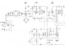
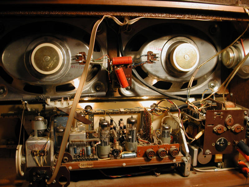
McIntosh entwined a 12AT7/ECC81 section with a 6DS4 nuvistor as the TRF front end in their well respected MR71 tuner. I've uploaded a snip of the MR71's front end.
Attachments
Last edited:
Kevin,
I too own a MR71. It's 1 of the very best, ever.
Given the DIY nature of this board, the members might want to give Dan Schmalle, AKA Doc B, at Bottlehead Corp. a nudge regarding the article John (Buddha) Camille wrote about hotrodding the Dyna FM3. Buddha really tore into the "beast". Among other things, he used a cascoded 6922 as the TRF front end. It just might be monkey see monkey do time.
Last edited:
Mallory (the capacitor company?) made those "Inductuners";
Mallory made the Inductuner that went into the Boonton RF signal generators we had in the lab back in the late 70's. The same Mallory that made capacitors and automotive ignition systems, including the entire distributor.
Plug the word INDUCTUNER into Ebay. You will find several old ads and an auction with 7 old inductuners for sale
I have a tubed multiplex adaptor board from some old japanese tuner or receiver. Uses a 12AU7 and a 6AU6. Looks complete but no tubes or other info. $25 shipped.
Email me for a pic if interested stellavox@excite.com
Email me for a pic if interested stellavox@excite.com
Sounds great Osvaldo, have you got any picture or schematics for inspiration?
Cheers
Matt.
Photos still not because it is only an idea, but if you have any machine capable of run DOS's edit.com, I have the schematic proposed and the calculae for inductances made in ASCII CP437 if you want it.
HI
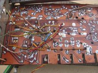
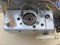
I would like myself to have a tube FM radio, and i found this old and in very bad conditions, but maybe i could use some parts to make the tuner, and i am only interested in FM. I know this is a Telefunken chassis, but dont know the model,in order to try to get the shematic of it ! By the photos can someone help me ? wich model is this ?
Thanks a lot
Attachments
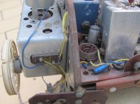
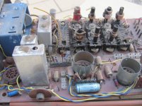
Two more photosHI
I would like myself to have a tube FM radio, and i found this old and in very bad conditions, but maybe i could use some parts to make the tuner, and i am only interested in FM. I know this is a Telefunken chassis, but dont know the model,in order to try to get the shematic of it ! By the photos can someone help me ? wich model is this ?
Thanks a lot
Attachments
Most of the old radios have only one pre-selector (2 ganget capacitor)...to make a good tuner it takes at least 3 preselectors (4 ganged capacitor). However...you can have fun using your parts...they are not worthless.
Just my 10cent
Edit...I think its a Telefunken Concertino 5384W
Just my 10cent
Edit...I think its a Telefunken Concertino 5384W
Last edited:
Thanks, it looks similar, but it is other model ,i can see some diferences in the chassis, but the FM tuner looks the same, and it is not capacitor tunning, but is inductor tunning. Any idea where i can get the schematic of this 5384 W ? Many ThanksMost of the old radios have only one pre-selector (2 ganget capacitor)...to make a good tuner it takes at least 3 preselectors (4 ganged capacitor). However...you can have fun using your parts...they are not worthless.
Just my 10cent
Edit...I think its a Telefunken Concertino 5384W
Far be it for dampening your enthusiasm for "scratch building" an FM tuner but besides the IF (and multiplex) transformer issues there is the "front end".
Unless you are going to try multiple varicap diodes (and their attendant tracking issues) you would need a 3 to 5 section variable tuning capacitor. Try to find one of those these days. Then, how do you plan to mechanically operate it - and what kind of dial might you use? Without multiple, tunable RF stages in the front end, tubes can have serious problems with intermod distortion in urban environments
If you can "let go" of total scratch building, you could look into scavenging sub-assemblies (front ends, IF transformers) from scrap or non-working tuners. Both Fisher and Scott made some nice tubed front end modules - Fisher used multiple nuvistors. The Dyna FM-3 has a very decent IF /detector board.
Regarding tubed-multiplex decoders, the designs I've seen and used suffered from limited separation, especially in the high frequencies, which seemed to make the hall "V" shaped and added distortion. The second-generation decoder chips are fine from that perspective and don't need weird coils. Get the low level audio signals out of them, bypass any internal op amps, and follow up with a tube-based line amp.
Depending upon the type of detector you plan on using, you may also have to think about having multiple limiting stages.
Then there is the alignment issue - especially in the IF strip. Getting multiple transformers to "line up" (overlapping wide band designs or stagger tuning narrow band designs really requires a swept signal source to do it right). That's why designers dropped tuneable coils, like hot potatoes, for ceramic filters.
For a number of years I played FM reception games with surveillance receivers. Most of them covered the commercial FM band and earlier ones used nuvistors in the front end if not throughout, with 3 to 5 stages of permeability tuning (tuning the L instead of the C - like old car radios). Nems-Clarke, Communication Electronics Inc (CEI) made nice tubed units. As there were typically lots of unnecessary circuitry in these receivers, DIY scavenging and simplifying is a distinct possibility.
But with the continuing degradation of the medium's sound quality, I have basically given up on FM.
Have fun in any case.
Charles
Another source may be military surplus front end multi ganged air caps. But I digress, doing so is troublesome to say the least. Sadly we don't have the likes of Dolby FM these days and with the industry standard of quality going down the tubes, well, I wouldn't, but not saying you shouldn't
Thanks Regenpak, yes, this model 5306 looks like the chassis i have, i Googled a lot, but no luck with schamatic.Look around a bit more, I found another Concertino, 5306, which also looks similar.
Then you didn't google hard enough. Miss Tanya has the schematic (pilfered from hifiengine.com). Fascinating how Telefunken implemented the stereo decoder. A single pentode (6BH6) amplifies the 19 kHz pilot tone, doubles it to 38 kHz, then amplifies it again to drive the demodulator. Nice piece of engineeringThanks Regenpak, yes, this model 5306 looks like the chassis i have, i Googled a lot, but no luck with schamatic.
Thanks a lot Regenpak !! Now i can try to put this chassis to work again, but i will try to use only the FM parts to make my tuner,It will be my project for next winter, because now here it is too hot to work with tubesThen you didn't google hard enough. Miss Tanya has the schematic (pilfered from hifiengine.com). Fascinating how Telefunken implemented the stereo decoder. A single pentode (6BH6) amplifies the 19 kHz pilot tone, doubles it to 38 kHz, then amplifies it again to drive the demodulator. Nice piece of engineering
( 39 Celsius today ).- Status
- This old topic is closed. If you want to reopen this topic, contact a moderator using the "Report Post" button.
- Home
- Amplifiers
- Tubes / Valves
- New Production Tube If Transformers from Germany