hello FDA-1 user!
I am looking for the best combi of cap´s in the output
the input-impendance of the most pre´s is 10-100K!?
What do you think about one silmic 100uf +10uf pio+0,01uf pio? It’s a compromise ?
I've seen some have used jensencaps?
pleace helb me to find a combination
pio´s in 10 uF i have here!
thanks for helbing
regards
florentino
The best caps are NO caps
")
I´m listening to FDA-1B OCL! After one week of burn in, just shorted the output caps an set DC offset to 0mV (+-1mV). Sounds great, more focus and more 3D!
apoo
Hi folks,
i was very impressed of the dynamics of this DAC from very beginning, but the sound was after a short time of listening fatiguating. I´ve changed the i/v resistors with dale resistors and PIO capacitors K40Y-9. This was better but not enough. I decided to try batteries.
These are the changes:
- OCL! all output caps shorted, DC offset adjusted to 0mV
- analog supply PCM1794A - two separate belleson +5v reg with LiFePO 2x3,3v
- digital supply PCM1794A - two separate LiFePO @3,3v
- a huge improvement in sound was the battery supply for the discrete IV! 4x24v lead-acid batteries
- 12v lead-acid for the receiver
The WaveIO USB receiver (XMOS) i´m using is also fed with 6v lead-acid and a 2A-5V belleson reg. The onboard isolator with 3,3v LiFePO
The change is huge! It´s another DAC! It´s not fatiguating at all, it has tremendous dynamic and the treble is not so "hi-fi" like. Bass is very, very controlled and deep. It´s maybe the best DAC i´ve heard for a long time!
Give it a try!
Attachments
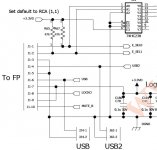
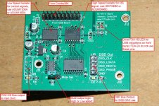
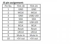
Add a RX-V8 interface board for Amanero Combo384 to FDA-1B and FDA-2A. Details can be found in below link:
RX-V8 Interface Board from “Amanero USB-I2S module” to FDA-1B or FDA-2A DAC
RX-V8 Interface Board from “Amanero USB-I2S module” to FDA-1B or FDA-2A DAC
Attachments
Short pin 1 and pin 2 of J1 to pin 3 (ground) to have default = (0,0) or I2S as input from J5. Short R171 to un-mute the I2S input or use the pin 9 of J5 to control the mute from external source. Mute is active High.
hey. i've got the FDA-2 from you, and soldered it an tested it now. i guess this is the same for FDA-2 as for FDA-1?
Pin 3 is also an input pin for FDA-2. Pin 3 can be short to ground using R97 (default become 0 = ground).
When R97 is shorted, then short R107 and open R106 to have same function as FDA-1B.
FDA-2 is more flexible to have 5 input or 4 input and thus jumper(or resistors) need to be set properly. Of course a new control board is required.
When R97 is shorted, then short R107 and open R106 to have same function as FDA-1B.
FDA-2 is more flexible to have 5 input or 4 input and thus jumper(or resistors) need to be set properly. Of course a new control board is required.
Hi,
I just have a fda 1B ( buy to a forumer for christmas) and i would like to know :
1) what is the function of the resistors 4R99 ( like R130) behind the analog out of the dac pcm1794 ?
2) I have a clock 11,286Mhz /5V from tentlabs. Can i use it with his own power supply and few modifications of the asrc card ? I want use the dac in a first time only with a cdpro at 44.1 khz.
3)Is that possible to have the schematics of the asrc board ?
bruno
The circuit of the ASRC BD is here:
http://www.fetaudio.com/wp-content/uploads/2012/05/FP7-ASRC-Ckt.pdf
Regarding clock to the ASRC, it is a 24.576Mhz XO. Not sure if you can use 11.286Mhz or not.
http://www.fetaudio.com/wp-content/uploads/2012/05/FP7-ASRC-Ckt.pdf
Regarding clock to the ASRC, it is a 24.576Mhz XO. Not sure if you can use 11.286Mhz or not.
I'll try to sold together pin 2 and 3 of the src4192 and so, Mck Out will be the same of XO frequency and that would be working with your pcb.( I have one src4192 in my stock of parts but no ad1896)
and about the function of the resistor 4r99 at the entry of the I/V stage it's a secret ?
In a first time I have think this resistor is using for decrease the entry impedance of the stage i/v but on the MicroCap8 simulation, it's not the case.So I don't understand what is this function.
and about the function of the resistor 4r99 at the entry of the I/V stage it's a secret ?
In a first time I have think this resistor is using for decrease the entry impedance of the stage i/v but on the MicroCap8 simulation, it's not the case.So I don't understand what is this function.
Regarding the output resistors to the IV, there is someone take some measurement and analysis on that in this forum. The findings is that driving a resistor IV up to 50 ohm to ground will not increase the distortion level much.
In my case, I find that putting the resistor in will ensure the distortion will be minimum at all situations. As you can see my design is not driving the output to a virtual ground but rather a positive reference set by the diodes. After doing that, the distortion is more consistent and low. Thus the resistor effect is minimized and become just a crossover of signal. I think if you are interested, you can change the value to see if you can hear any sound difference. I did not tried all possibility as it is a very time consuming process.
In my case, I find that putting the resistor in will ensure the distortion will be minimum at all situations. As you can see my design is not driving the output to a virtual ground but rather a positive reference set by the diodes. After doing that, the distortion is more consistent and low. Thus the resistor effect is minimized and become just a crossover of signal. I think if you are interested, you can change the value to see if you can hear any sound difference. I did not tried all possibility as it is a very time consuming process.
Has somebody interest for buying my full assembled and working FDA-1B with both ASRC boards? External i2s prepared for WaveIO, Dale i/v resistors and russian PIO capacitors. No output capacitors. Eventually a Schuro encapsulated and ground-shielded toroidal transformer 230v-2x18v 65VA. Delivery from Germany. I´ve payed for all parts, inkl. transformer 560$ / 430€. Please PM me for offers!
apoo
apoo
- Status
- This old topic is closed. If you want to reopen this topic, contact a moderator using the "Report Post" button.
- Home
- Source & Line
- Digital Line Level
- New PCM1794A Kit – Balanced Mode Update – Good to Fantastic Sound!