Hi Spencer,
Sounds like a good design in that case. There are about as many ways to go about I/V conversion as there are designers.
You should listen to that DCD-S10. Did you know it also has external digital in and out? It also has a balanced output, so it's very versatile on the bench (where mine started life, it's now on my best system). That should allow you to compare it on a one on one basis. Like your friend, I'm still extremely pleased with it. I've also had other DACs that friends have brought over to compare. So far the Denon has sounded the best - overall consensus from many people. It's a winner.
I hope to hear a better DAC section some day. Something I can use in other places (I miss it on the bench).
-Chris
I have two pictures to show how I take the measurement of the voltage Vpp at the output pin of the PCM1794A. It is about 60mVpp with Ipp 7.8mA and thus giving an impedance of 7.8 ohm. Minus the 4R99 in series at I/V input and thus the input impedance is about 2.8 ohm at the BJT I/V. Note that the noise at the PCM1794A Iout pin is not that much as the scope bandwidth is set to 400MHz.


I have two pictures to show how I take the measurement of the voltage Vpp at the output pin of the PCM1794A. It is about 60mVpp with Ipp 7.8mA and thus giving an impedance of 7.8 ohm. Minus the 4R99 in series at I/V input and thus the input impedance is about 2.8 ohm at the BJT I/V. Note that the noise at the PCM1794A Iout pin is not that much as the scope bandwidth is set to 400MHz.
View attachment 189134
View attachment 189135
Hi Spencer
I am assuming you are asserting that a lower impedance value is better. If that is the case, why not take the series resistor out completely?
Best wishes
TC
Hi Spencer,
Good idea to allow a resistor to linearize the input resistance of the transistor I/V. Can you please clarify your current measurement for me? Is that a peak to peak value of current change?
Hi TC,
I guess from my post you had some idea why the resistor exists. There may also be some minimum resistance that something wants to see. Not being familiar with these exact parts, I'm not going to hazard any guesses there.
-Chris
Chris,
I inject 0dBFS 1kHz digital signal to the SPDIF input from my AP and check the waveform at pin 3 of PCM1794A and you will see 60mVp-p signal as shown on scope. If you prob the input of the Jfet I/V (after 4.99ohm resistor), the wave form become about 20mV. So the current across the 4.99 ohm is about 40mA/4.99ohm or 8mA peak to peak.
I also check the waveform at the 472 I/V resistor and it is about 3.8Vp-p. So it confirm the 8mAp-p current again.
Let me know if you have other questions or measurement that you want to know.
Spencer
Hi Spencer,
Good idea to allow a resistor to linearize the input resistance of the transistor I/V.....
Hi TC,
I guess from my post you had some idea why the resistor exists. There may also be some minimum resistance that something wants to see. Not being familiar with these exact parts, I'm not going to hazard any guesses there.
-Chris
Hi Chris
Thanks for your reply. I think you said in an earlier post there are numerous designs out there. Perhaps each is unique in its own way catering for a particular audio need. I guess that is why hifi is personal in taste.
Anyway, I am getting a little restless and looking at ways to play around with the board. In my mind, reducing the impedance should improve performance but perhaps this may introduce other problems.
Oh, why do NP's designs have 15 ohm impdeneces? By design or due to the components he uses.
Have a good weekend.
Best wishes
TC
Big Caps!
Hi
Look what the Postman brought today!
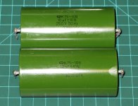
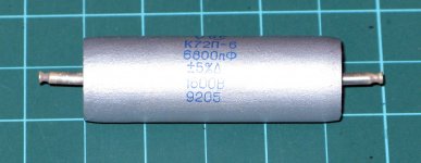
I will be replacing the 8 6800pf caps with these 1600V Teflon ones ….whoa!! Yes 1600V – crazy, I know. I will also be trying out the monster K75-10’s too.
I think the Teflons should be very interesting and the K75 is a hybrid PIO - PLIO??
This is going to be an interesting weekend!
Best wishes
TC
Hi
Look what the Postman brought today!
I will be replacing the 8 6800pf caps with these 1600V Teflon ones ….whoa!! Yes 1600V – crazy, I know. I will also be trying out the monster K75-10’s too.
I think the Teflons should be very interesting and the K75 is a hybrid PIO - PLIO??
This is going to be an interesting weekend!
Best wishes
TC
Attachments
Hi TC,
Don't forget that large capacitors are basically antennas that might either pick up or radiate stuff you don't want to know about. That seems to be one of the huge mistakes that are made around the world. If you look carefully at circuits designed for these capacitor types, they are either not at risk for noise pickup (radiation is another matter completely), or they have designed a space for those parts where they are shielded from other signals, or signals that may be radiated from those caps. I'm talking about metal shields or metal enclosed areas in the circuit.
Component selection can be tricky business. Don't forget about the obvious problems either.
In case you are wondering why large capacitors can be a problem, think about one of the two capacitor connections. It is connected to the outer foil, and so acts in the same way that a sheet of copper would the same outer dimensions. Now, if you would never connect a sheet of copper in that location, why would you do the same thing using something that simply looks different?
-Chris
Bigger Not Better?
Hi Chris
I am aware of the interdependencies and how they can affect sound but I thought the main culprit were the TXs. That was why when mounting the two boards, I was concerned that the TXs were too close and whether using two would add more noise (phase, EMF interaction, etc) as I have no equipment to measure it.
As far as my audible experience goes, I don't believe these biggies have had a negative impact. In fact, the experience has been to the contrary. However, that is not to say there isn't or the designs were optimized to begin with. Maybe I am just not hearing them – selective listening ha ha!!! Perhaps on the bench, the measurements may be worse, and I am sure they will be L.
Anyway, I am glad that you raised this. At least I am more aware of the possible downside. However, as I have them already and they are very easy to install, I shall give them a try anyway ….. Perhaps someday, I will have the ability to measure the impact.
Thanks again.
Have a good weekend…
Best wishes
TC
PS. I like your tag line ... how true .. how true. That's why many of my purchases have been vetoed! "No, not another box in the house, dear!!!"
PCM1794a Kit - Another Field Report
Hi everybody,
let me short tell about my experience with the PCM1794a kit.
My listening experiences with digital sound many years ago (compact disc aera) were extremely frustrating and so I did not pay any more attention to digital technology.
Two years ago I started to explore the potential of hi-res digital audio. I went with an Apogee Rosetta feeded by a Ubuntu box with a realtime kernel and was more or less satisfied, means it was okay but still had not the live character that Vinyl has.
So I read a lot about different DAC chips, I/V conversion, amplification and all that stuff. I decided to build one of those diy kit and ordered the PCM1794a balance kit from Spencer 4 weeks ago. Although the parcel was immediately sent (I had the tracking number) I did wait a long 17 days until it finally arrived in Switzerland. The kit gave a good impression on me, gold-plated pcb, parts were complete and properly labelled and I got e-mailed the latest version of the manual.
Well, I soldered all the parts together which took some hours, made the calibration of the I/V supply voltage and the output dc offset which was not a problem at all and connected the kit to my Office PC to burn it in for an hour. Sound was there, everything looked fine. After that I recalibrated the output dc offset which hardly changed and connected the kit to my hi-fi system. Well - I was excited, that thing is in a different league. Music is vivid, sounds more natural, the sound stage is wide, details are here, and listening is a real pleasure, very very close to Vinyl or maybe even there ...
As a next step I will give different output caps a try. At the moment there are no output caps which is a small risk but since I have output transformers to connect the balanced output to the single ended input of my preamp latter is protected.
Last word: I can highly recommend the PCM1794 to everyone looking for a good-sounding DAC.
Mono mode
Hi Spencer,
I am glad to see you posting your advanced design here. I have a question about The PCM1794a in mono mode. I'm sure I will eventually want your dual boards to hear a cutting edge active I/V but for right now I have a versatile test sled in the "Big Dac Board" that I am using for experiments that sounds quite good with DIR9001 (sounds better than CS8416 in this application) and CS43122 (better than 4398 according to the designer so I didn't try that chip). The next thing I want to try is a passive transformer I/V using PCM1794a with it's outputs paralleled to take advantage of the increased current level. Would you recommend using a small series resistance on each output to isolate it from power hogging and offset currents or can I just parallel the identical outputs in mono mode to double the available current to the same I/V resistor which should get me all the way down to 10-20R with a 1:8 transformer.
-way better jitter rejectionDIR9001 (sounds better than CS8416 in this application)
-if you care even a little bit about channel matching, you shouldn'tThe next thing I want to try is a passive transformer I/V using PCM1794a
")
Channel matching
What happens to channel matching?
if you care even a little bit about channel matching, you shouldn't
What happens to channel matching?
Scott,
I have not try to parallel PCM1794A current output and thus I cannot comment much. But if you want to try, I think measurement is the only way to confirm if it is better or worse. A FFT scan is very important to see how the distortion changes. For the series resistor in the BJT I/V, it is used to supress some harmonics spike that I see from the FFT measurement and thus a small value resistor is added.
I have not try to parallel PCM1794A current output and thus I cannot comment much. But if you want to try, I think measurement is the only way to confirm if it is better or worse. A FFT scan is very important to see how the distortion changes. For the series resistor in the BJT I/V, it is used to supress some harmonics spike that I see from the FFT measurement and thus a small value resistor is added.
What happens to channel matching?
-without resistor IV , its goin to look bad, tolerance? Theres a commercial example somewhere with plots published, it was enough to deter one of my friends.
-with resistor IV you might exceed the output voltage compliance and the switches inside for current sources (diodes ) goin to suffer , introduce linearity errors in turn. ( I assume pcm1794 has r2r roots?)
Last edited:
Hi All,
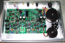
I also got a Balance kit from Spencer. The kit came well packed and marked. I just finished soldering the components (except the output coupling caps) and now looking for some hookup wires. Attached is a photo of the layout, unfortunately there is not much space so the trans (maybe should look for smaller ones, but these were my spares) are very close to the PCB.
Regards
Victor
Attachments
Denon
Hi Chris
I have been looking for a good transport to eventually succeed my aging Sony ESD 337. This uses the KSS 190 drive mechanism. I really love it as the laser and tracking are magnetic. I had many years of enjoyment using it. About a year ago, the rubber belt controlling the loading tray gave way. I thought I had it but after minor surgery, I managed to replace it.
Does your Denon's 240A have the same magnetic laser head control? From what you have written, is seems like it is good as is without a DAC. I am sure I can find out easily but how many and what type of inputs does it have?
Best wishes
TC
Hi Spencer,
The electronics are very good, the transport is a Sony KSS-240A type. Too bad this CD player didn't use those really nice NEC CD transports. This machine is very close to DCD-3000 and a few others with the centered
-Chris
Hi Chris
I have been looking for a good transport to eventually succeed my aging Sony ESD 337. This uses the KSS 190 drive mechanism. I really love it as the laser and tracking are magnetic. I had many years of enjoyment using it. About a year ago, the rubber belt controlling the loading tray gave way. I thought I had it but after minor surgery, I managed to replace it.
Does your Denon's 240A have the same magnetic laser head control? From what you have written, is seems like it is good as is without a DAC. I am sure I can find out easily but how many and what type of inputs does it have?
Best wishes
TC
Hi TC,
The KSS-240A transport uses the same gear driven mechanism that most of that style transport uses. Nothing spectacular there, but it works well. I would rather have a better transport, but there just aren't any out there anymore.
The Sony ES machines are not something I would want either. They are overly complicated and suffer from the same problems that plagued Sony from the start. That company never seems to learn from their past mistakes and will often lie to cover up their own design problems. You have to watch silly things like lubricating grease becoming stiff, broken gears .... on and on. There is no excuse for that company. I hate to say it, but those KSS-210A and KSS-240A transports at least work and are repairable. That's pretty sad.
The base transport using a linear feed motor (magnetic head you referred to) is a KSS-151A. This is another excellent head, but didn't like warped CD's too much from what I've heard. Tascam and Denon both used these, and probably many others as well.
Technics uses a linear feed motor type head and it appears to be reliable. Too bad their audio section is so painful to listen to. Truly bad (another meaning for MASH technology? )
The Denon DCD-S10 was "blow me away" good when I first heard it in comparison to anything else I had heard. So this many years later, I still can't find anything that really sounds better. It has the D/A circuits that the Nakamichi OMS-7 should have had (had they existed yet!). The OMS-7 uses a Philips 14 bit chip set (TDA-1540). Nakamichi made it sound better than the 16 bit systems that were out then. It still sounds good, but the Denon kills it.
One thing everyone should understand is that the sound begins with the RF pattern coming off the CD. If this is compromised, it will not sound good. The one thing I saw decline over the years was the quality of the RF (Eye) Pattern.
-Chris
The KSS-240A transport uses the same gear driven mechanism that most of that style transport uses. Nothing spectacular there, but it works well. I would rather have a better transport, but there just aren't any out there anymore.
The Sony ES machines are not something I would want either. They are overly complicated and suffer from the same problems that plagued Sony from the start. That company never seems to learn from their past mistakes and will often lie to cover up their own design problems. You have to watch silly things like lubricating grease becoming stiff, broken gears .... on and on. There is no excuse for that company. I hate to say it, but those KSS-210A and KSS-240A transports at least work and are repairable. That's pretty sad.
The base transport using a linear feed motor (magnetic head you referred to) is a KSS-151A. This is another excellent head, but didn't like warped CD's too much from what I've heard. Tascam and Denon both used these, and probably many others as well.
Technics uses a linear feed motor type head and it appears to be reliable. Too bad their audio section is so painful to listen to. Truly bad (another meaning for MASH technology?
)The Denon DCD-S10 was "blow me away" good when I first heard it in comparison to anything else I had heard. So this many years later, I still can't find anything that really sounds better. It has the D/A circuits that the Nakamichi OMS-7 should have had (had they existed yet!). The OMS-7 uses a Philips 14 bit chip set (TDA-1540). Nakamichi made it sound better than the 16 bit systems that were out then. It still sounds good, but the Denon kills it.
One thing everyone should understand is that the sound begins with the RF pattern coming off the CD. If this is compromised, it will not sound good. The one thing I saw decline over the years was the quality of the RF (Eye) Pattern.
-Chris
Transports
Transports are now completely obsolete for me since I started using my hard drive out through the spdif of a Firewire410. The sound is better than my best burns on Mitsui gold discs read by my EAD T1000 transport. I was a hold out for years but now realize what I was missing. Better sound and the convenience to play more music, more often.
.
.
Hi TC,
The KSS-240A transport uses the same gear driven mechanism that most of that style transport uses. Nothing spectacular there, but it works well. I would rather have a better transport, but there just aren't any out there anymore.
The Sony ES machines are not something I would want either. They are overly complicated and suffer from the same problems that plagued Sony from the start. That company never seems to learn from their past mistakes and will often lie to cover up their own design problems. You have to watch silly things like lubricating grease becoming stiff, broken gears .... on and on. There is no excuse for that company. I hate to say it, but those KSS-210A and KSS-240A transports at least work and are repairable. That's pretty sad.
The base transport using a linear feed motor (magnetic head you referred to) is a KSS-151A. This is another excellent head, but didn't like warped CD's too much from what I've heard. Tascam and Denon both used these, and probably many others as well.
Technics uses a linear feed motor type head and it appears to be reliable. Too bad their audio section is so painful to listen to. Truly bad (another meaning for MASH technology?
The Denon DCD-S10 was "blow me away" good when I first heard it in comparison to anything else I had heard. So this many years later, I still can't find anything that really sounds better. It has the D/A circuits that the Nakamichi OMS-7 should have had (had they existed yet!). The OMS-7 uses a Philips 14 bit chip set (TDA-1540). Nakamichi made it sound better than the 16 bit systems that were out then. It still sounds good, but the Denon kills it.
One thing everyone should understand is that the sound begins with the RF pattern coming off the CD. If this is compromised, it will not sound good. The one thing I saw decline over the years was the quality of the RF (Eye) Pattern.
-Chris
- Status
- This old topic is closed. If you want to reopen this topic, contact a moderator using the "Report Post" button.
- Home
- Source & Line
- Digital Line Level
- New PCM1794A Kit – Balanced Mode Update – Good to Fantastic Sound!