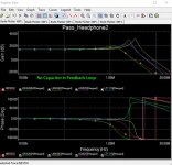
The feedback capacitor shown as 100 pF may need to be adjusted. With the circuit as shown with +- 17 volts and the OPA2604 I used no capacitor. Simulation will get you close but it varies due to layout, voltage rails and output devices chosen. 6L6 had slightly different results than I did but if you have access to a scope that will let you see how it looks.
Unless labeled otherwise all resistors are .25 Watt.
Unless labeled otherwise all resistors are .25 Watt.
Some more simulated results. The old standby NE5532 is most tame with this circuit. You might want to adjust the values of the gate stopper resistors lower, depending upon the capacitance of the output devices.
Attachments
Last edited:
Thanks Jim.
Here's my crazy idea: I built the BA-3 front end as a preamp. I need a headphone amp and the BA-3 FE doesn't cut it for my Grados. I am thinking I need to add an output stage to the BA-3 for headphone use. The output stage from this headphone amp looks promising.
I want to run the BA-3 front end straight into the output stage and keep it all in the same case and (hopefully) use the same 24V+/- PSU. Sound like a good plan? Worst case scenario I can set up a second reg at 15V for the output stage if 24V isn't a good idea.
I can see some sort of feedback loop on the output back to the IC on this headamp. I would not have that in my BA-3 plus output stage scenario. Any issues with that? I am guessing it's just for feedback use in the IC and I could ignore it.
I was thinking exactly the same.
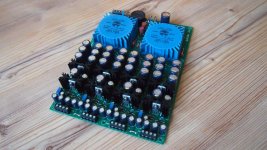
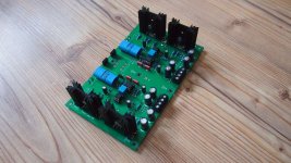
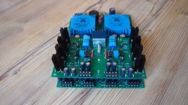
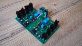
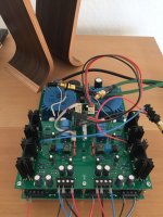
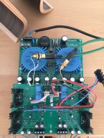
I built the output follower stage only, made a quick PCB.
Attached it to my BA-3-FE and it sounds lovely with my DT990 pro 250 Ohm headphone. I lowered the 10 ohm to 3.3 Ohm like Patrick suggested.
Bias is then around 180mA. I don't hear a difference between PSU at 24V or PSU at 15V. There is a lot more heat at 24V though
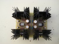
 At 15V 180mA little sinks get around 38C at 24V around 49C.
The output offset is fantastic low, well regulated by the optocoupler circuit.
Though the + and - voltages do have to be exactly the same, otherwise you get more offset. I have around 4 mV and 18mV offset on the left and right channel.
You can tune the offset by varying the 10K: R6 or R24 a few ohms.
I used Vgs matched FQP3N30 and FQP3P20's. They fit right in, no adjustments of component values.
Downside is, the combination BA-3 and this follower has too much gain for a HPA. I listened at 1/3 level all the time.
So better find a FE with less gain, say 6dB - 10dB.
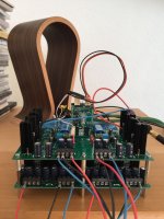
Next is to try this follower with my Edcors PC60015K's and a JFET buffer, so you have basically a M2 HPA
And also the VFET pt2 frontend I'm going to try, with and without feedback.Attachments
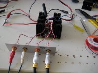
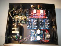
Power up my Headphone Amp today
No hum and noise. Very nice sound with my AKG K812. I (short) tested following OPA:
- OPA604
- AD8610
- LM47910
Thanks Wayne for supporting the DIY community!
Next step is to build a enclosure and solder a new board with Clarity ESA and Dale CMF55.
No hum and noise. Very nice sound with my AKG K812. I (short) tested following OPA:
- OPA604
- AD8610
- LM47910
Thanks Wayne for supporting the DIY community!
Next step is to build a enclosure and solder a new board with Clarity ESA and Dale CMF55.
Attachments
... I lowered the 10 ohm to 3.3 Ohm like Patrick suggested.
Bias is then around 180mA. I don't hear a difference between PSU at 24V or PSU at 15V. ...
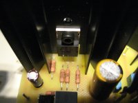
Oh nice. I will icrease the current. 6L6 do you have any experience with your build ?
With 10 Ohm resistors, my heatsinks are very cold

Daniel
I was thinking exactly the same.
I built the output follower stage only, made a quick PCB.
Attached it to my BA-3-FE and it sounds lovely with my DT990 pro 250 Ohm headphone. I lowered the 10 ohm to 3.3 Ohm like Patrick suggested.
Bias is then around 180mA. I don't hear a difference between PSU at 24V or PSU at 15V. There is a lot more heat at 24V though
The output offset is fantastic low, well regulated by the optocoupler circuit.
Though the + and - voltages do have to be exactly the same, otherwise you get more offset. I have around 4 mV and 18mV offset on the left and right channel.
You can tune the offset by varying the 10K: R6 or R24 a few ohms.
I used Vgs matched FQP3N30 and FQP3P20's. They fit right in, no adjustments of component values.
Downside is, the combination BA-3 and this follower has too much gain for a HPA. I listened at 1/3 level all the time.
So better find a FE with less gain, say 6dB - 10dB.
Next is to try this follower with my Edcors PC60015K's and a JFET buffer, so you have basically a M2 HPA
Thanks for sharing, Walter. I was worried about gain too. Guess I will have to rethink things. Have you tried just the B1 buffer in front of the output stage?
- Status
- This old topic is closed. If you want to reopen this topic, contact a moderator using the "Report Post" button.
- Home
- Amplifiers
- Pass Labs
- New PassDIY Headphone Amp (now available)