Hi Brian, almost a year later...
I put together one of the lm1875 amplifiers using your PCBs. I have gone with the basic setup to get things going and plan to add zobel etc. later.
Currently on each amplifier PCB I have the lm1875 chip, 22kohm on R2 and 1kohm on R3, and 22k on R4 for feedback, with 2x 0.1uf and 2x 47uf decoupling caps, that is all. I have jumpered C1, C2 and R6.
My DC at output is the same as at input! Power supply is fine, and signals pass via a 50kohm pot.
Do you have any advice on why the output voltage would be the same as the input?? Would I have blown the chips?
Also, there is a buzzing sound near AC in the chassis, could be the transformer. Any input would be appreciated, thanks!
Ahh nevermind, I did blow the chips! Lucky I bought a few extras...
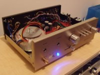
Amplifier sounds beautiful even when breaking in. Using a 120VA 18v toroid which idles at 20.8 (as specified by manufacturer) this is ideal for my 6ohm speakers. The input is inaudible with volume turn down and barely audible at full volume! This is a very satisfying build.
Just a thought, bass is a bit thin, I increased the lower frequencies in foobar which is balancing the sound nicely, perhaps a slight increase in filter capacitance is in order, what thoughts on this?
Attachments
I have exactly the same problem as swin1, DC on output is the same as the supply DC. Fully populated amp board except for jumpered R6. When I jumper R6 (input & output ground?) the DC on output disappears but there is NO output at all. Removing the optional components makes no difference. I think my only mistake was initially using a 25-0-25 toroid (now replaced with 18-0-18) which may have been too high a voltage and fried the chips? I have spare replacements on the way but I'm dying for answers in the meantime!
These things seem to always work for me.
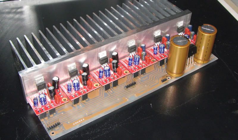
i have made this carrier for a musical instrument project. they are actually to electromagnetically inject signals in to guitar strings.
Neutron Physical Guitar Synth.
because of the possibility of blowing one i made them able to be swapped out by just unscrewing the 1875 and unplugging it from the headers.
There is an option for a star ground on the inputs if it is too noisy using the in/out ground strap.
This is not quite complete, i am waiting for nylon screws and mica washers, but the amps all work fine when tested with no hum, but who knows what will happen once it is in the case with all the other compontents (8 channel ADAT AD/DA converter, some MIDI stuff etc.
Moonbird, I have yet to see a schematic for this kit. There is a component guide available here. I am currently putting Mouser order together that I would be happy to share with you.Hi all - Any further word on this amp? I bought a set of these chipamp.com boards and a PT from a guy on EBAY. Did the manual / schematic ever get completed? Thanks very much!
Cheers,
Alan
Badly.
But seriously, the 1875 has a maximum output of 3Apk when it is cold. The limit will reduce at elevated temperatures.
If you use a 4 chip bridged parallel assembly each chipamp sees a load equal to your actual load.
The best you can get is ~6Apk into 4r0. About 72W into 4r0.
Into a real speaker you would need to double the chip count to 8, or preferably 12, i.e. 6off in parallel and then two sets bridged.
Badly.
But seriously, the 1875 has a maximum output of 3Apk when it is cold. The limit will reduce at elevated temperatures.
If you use a 4 chip bridged parallel assembly each chipamp sees a load equal to your actual load.
The best you can get is ~6Apk into 4r0. About 72W into 4r0.
Into a real speaker you would need to double the chip count to 8, or preferably 12, i.e. 6off in parallel and then two sets bridged.
Thank you
I am currently putting Mouser order together that I would be happy to share with you. -- Alan
So sorry I stopped following this thread -- a belated thank you for your kindness.
")
Hi all,
I'm going to start making my LM1875 soon using a 12-0-12 300VA Transformer into 4 Ohm MA CHP-70s I noticed that on the component list on Page 2 it says;
C1 - 2.2µF (optional input capacitor)
C2 - 22µF bipolar (optional)
Shouldn't that be the other way round e.g.
C1 - 2.2µF bipolar (optional)
C2 - 22µF (optional input capacitor)
Jim
Last edited:
Dear Neutron,
[QUOTE}
Pic from initial prototype:
I will see if I can get pics posted from the assembled amp soon also.
[/QUOTE]
Looking at the above a Wima [Red] capacitor can be seen in the C1 position and a polarised electrolytic in the C2 position.
Somone should alter the list people [like me!] are going to be ordering the wrong stuff.
Jim
[QUOTE}
Pic from initial prototype:
An externally hosted image should be here but it was not working when we last tested it.
I will see if I can get pics posted from the assembled amp soon also.
[/QUOTE]
Looking at the above a Wima [Red] capacitor can be seen in the C1 position and a polarised electrolytic in the C2 position.
Somone should alter the list people [like me!] are going to be ordering the wrong stuff.
Jim
- Status
- This old topic is closed. If you want to reopen this topic, contact a moderator using the "Report Post" button.
- Home
- More Vendors...
- Chipamp
- New LM1875 pcb and kit pre-order special