Probably a silly question, but does the LDR board digitize the signal in order to control the volume and then convert it back to analog on the way out or does this just vary the resistance all in the analog domain?
Thanks
LDR is nothing but a resistor controlled by light , so the analog part is isolated from control.
Of course the resistor itself (from LDR) has some very specific proprieties and analog thats attenuated sounds very good.
How reproducible is the current into LED versus resistance cell resistance relationship in these LDRs? Is there any usage dependency, e.g. "light history" dependence? Does this relationship change over time so that you need to repeat the calibration or can you just do it once when assembling the unit?
Will this be a completely passive solution, or will there be a buffer or other active element?
Will this be a completely passive solution, or will there be a buffer or other active element?
Last edited:
In my experience the biggest factor is the ambient temp and that causes the most drift at the higher resistances. But of course as this is affecting all the LDRs the same so the net result is even across the controller.
cdsgames is adding temperature compensation so that should be minimised. So that should mean calibration is only required during the initial build to establish the base line for the LDRs.
I'm guessing this will be a passive solution otherwise it negates the idea of having minimal components in the signal path.
I'm running an Arduino version without temp comp and it works well.
LDR is nothing but a resistor controlled by light , so the analog part is isolated from control.
Of course the resistor itself (from LDR) has some very specific proprieties and analog thats attenuated sounds very good.
 That is an Opinion not everyone shares. Just saying
Finally we found out that Cds resistors have a skew depending on temp. So we put both boards inside aluminium casing for thermal inertia we waited 2h before calibrating and then we measured.
OK, you are making progress and conducting the right tests. Kudos. You are way ahead of others who have used LDRs for volume control.
I think you will find that both temperature and light history will both influence the resistance cell.
I would not trust the MFG data (e.g. datasheet Figure: Variation Ratio of Resistance vs Temperature). Did you verify the data? How consistent is that from part to part? I would not be too surprised about production variation causing deviations.
It's good to see someone finally paying attention to these little details. Keep at it.
Hi Charlie
The R/Temp is slightly different for each part but still linear. We are still testing.
Linear is good! It would take longer but you could do a 2 or 3 point calibration under several different temps for each part (heating or cooling them and waiting for equilibrium would take the longest) to obtain an accurate R vs temp calibration. You might be able to do a bunch of them at the same time so that when you have them equilibrated at some temp you can get your data point for a batch before starting the temp ramp to the next temp, etc.
If you can accurately correct for temp I think you would be in very good shape and way ahead of other LDR based volume controls in terms of tracking and accuracy.
Anything missing Gary ?
Fantastic and keep up the good work racing ahead of me now. Been pushed for time with other commitments.
Without pratical testing and just a few web pages a little hard to tell.
Might be nice to know roughly how you plan to package this. Given that there is RPi under the hood seems a shame to miss out on the IO control potential, standalone displays, remote control, source selection, standalone control via encoder etc etc. Or is it just going to be a passive volume control?
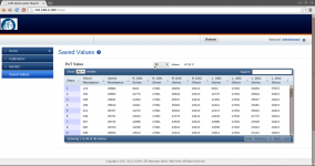
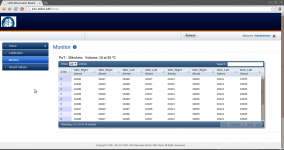
To the web pages:
Nice to see all the information and values listed.
The lowest shunt resistence seems quite high in terms of providing a nice mute and or a relay might pop as it is switched?
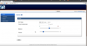
Does the user need to interact with the temperature compensation values? If so how do we choose the appropriate value?
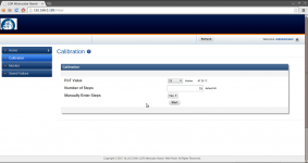
On the calibration page it would be nice to be able to select the potentiometer taper (log, lin etc.)
On the home page what is the significance of the pot value and temp comensate values? Day to day the sliders would be fine may be with a L & R displaying the pot resistance vs overal pot value.
Other options might be ramp speed, soft mute, soft power up to last vol, power to specific vol etc. Easy to get carried away
PM me if you want an off line discussion.
Gary
I was just about to start the Arduino LDR project.. Using an RPI would make much more sense. However for my use-case, I require multi channel attenuation.
Have you considered being able to daisy chain additional slave boards for multi-channel pre-amps? I'd imagine you would sell a fair few for people building active speakers.
Have you considered being able to daisy chain additional slave boards for multi-channel pre-amps? I'd imagine you would sell a fair few for people building active speakers.
I was just about to start the Arduino LDR project.. Using an RPI would make much more sense. However for my use-case, I require multi channel attenuation.
Have you considered being able to daisy chain additional slave boards for multi-channel pre-amps? I'd imagine you would sell a fair few for people building active speakers.
I'm sure it will be considered and added to the list if nothing else to support balanced line systems from there it relativley simple to expand.
I'm sure it will be considered and added to the list if nothing else to support balanced line systems from there it relativley simple to expand.
I would imagine all of the mini-dsp users would be clawing for one if so!
I was just about to start the Arduino LDR project.. Using an RPI would make much more sense. However for my use-case, I require multi channel attenuation.
Have you considered being able to daisy chain additional slave boards for multi-channel pre-amps? I'd imagine you would sell a fair few for people building active speakers.
You can daisychain using Ethernet..
- Status
- This old topic is closed. If you want to reopen this topic, contact a moderator using the "Report Post" button.
- Home
- Source & Line
- Analog Line Level
- New LDR for Rapberry PI