So, leave the hex hole as it is? It seem so small.
I bet Dietmars Peavey magnet has a larger hole than the hex hole. But I realize the Peavey magnet need a lot of work to look like the K55. The phase plug dome points in the wrong direction. Maybe he just switched places on the two center magnets. Will ask him.
I bet Dietmars Peavey magnet has a larger hole than the hex hole. But I realize the Peavey magnet need a lot of work to look like the K55. The phase plug dome points in the wrong direction. Maybe he just switched places on the two center magnets. Will ask him.
Last edited:
Imo, if you drill from the back, you will get metal splinters into the gap.
The picture in 242 is what I would expect to find inside.
The spacer idea is not new, the Radiian company does that on their drivers for some applications (they provide the spacer).
Btw, I think we should ask the mods to split this thread back a ways, since this is now a K-55 discussion not a Yamaha??
Any idea how wide the hole should be drilled?
Now I get why Radian wanted to use hot wax. Tape could be useful to dig out the remaining particles in the gap.
I wonder where to look for spacers. Maybe I can cut it out from paper or foil, or film.
Some companies manufacture spacers with photo etching: 0.1mm thickness metal spacer, View bearing spacer ring, zld-etched spacer Product Details from Shenzhen Zhuolida Electronics Co., Ltd. on Alibaba.com
sharp knife, metal "washer" of the right dimensions, and a suitably thick material.
Could be mylar, plastic, the right paper, etc...
Yes, anything that holds up long term is fine, but the inner diameter
needs to be bigger. The sheer hight gives more movement, but the
fact that it clamps more on the outside makes it equivalent to a softer
material lowering FS.
.
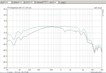
Radian,Here is a pic of the modified K55. Just a Peavey magnet structure glued
on with a little felt cavity attached to the vent hole.
Before is black and after the mod blue line:
What was the horn (if any) used for the before and after measurements, and at what distance and drive level?
Art
Attachments
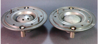
Say, Klaus, in post #50, what is being shown??
I see what looks like it might be the stock K-55 on the left, but what is on the right??
Also the WE555 has the dome inverted so that the concave side faces out the throat and faces into a conic phase plug. Wondering how that is happening on a Peavey motor assembly? And, for that matter, is this how the K-55 is set up as well??
_-_-
We got word from Dietmar.
We definetly are dealing with version 1 of the magnet structure as in post 73.
He said the cup is of soft iron and press fitted onto the pole plate. The alinco
magnet is 22mm long and has a 12mm hole. 12mm will not cause any unwanted
turbulences from the 2" coil.
We definetly are dealing with version 1 of the magnet structure as in post 73.
He said the cup is of soft iron and press fitted onto the pole plate. The alinco
magnet is 22mm long and has a 12mm hole. 12mm will not cause any unwanted
turbulences from the 2" coil.
Radian,
What was the horn (if any) used for the before and after measurements, and at what distance and drive level?
Art
It was done on his Sato horn.
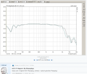
Here is his plane wave tube measurement
comparing the already mod.K55 with and without holes in the phase plug.
Pretty impressive work as he managed to the that sucker to about 5khz.
Attachments

Art,
The plane wave tube differential I think is shown in post #1??
This last post shows the modified driver vs the modified driver with holes in the phase plug.
I'm also interested to know which peavey driver is being used for the magnet portion?
Then what is the differential in reference sensitivity?
_-_-
Interesting that the mod shows hardly any LF improvement on the plane wave tube, but around 9 dB at 100 Hz increase on the Sato horn.
No no, the mod (bigger backchamper, peavey magnet, spacer) was done on both of the plane wave tube measurments. It just shows an additional mod
comparsion with holes in the phase plug vs. none holes.
Any idea what SPL the Sato with the modified driver can do at 100-150 Hz before reaching 10% distortion?
Dietmar did some calibrated measurements, the question is if they can be interpolated?
You certainly have lots of experience with measurements on horn/driver combinations and
I guess you would have a feel how a 1W distortion changes at 10W.
I ask him let's see what he answers.
Klaus
Quote:
Originally Posted by weltersys
Any idea what SPL the Sato with the modified driver can do at 100-150 Hz before reaching 10% distortion?
My measurements with horn/driver combinations has been primarily with high frequency compression drivers and cone driven mid and low frequency horns.
I used drivers similar to the Atlas midrange drivers in the mid 1970s, but never on any horns capable of the low frequency range of the Sato.
Dietmar certainly has done a remarkable job in extending and smoothing out the range the PD-5VH covers.
Generally, smoother response in a compression driver is achieved with a sacrifice in sensitivity.
It will be interesting to hear his answers regarding SPL and distortion.
Art
Originally Posted by weltersys
Any idea what SPL the Sato with the modified driver can do at 100-150 Hz before reaching 10% distortion?
Klaus,Dietmar did some calibrated measurements, the question is if they can be interpolated?
You certainly have lots of experience with measurements on horn/driver combinations and
I guess you would have a feel how a 1W distortion changes at 10W.
I ask him let's see what he answers.
My measurements with horn/driver combinations has been primarily with high frequency compression drivers and cone driven mid and low frequency horns.
I used drivers similar to the Atlas midrange drivers in the mid 1970s, but never on any horns capable of the low frequency range of the Sato.
Dietmar certainly has done a remarkable job in extending and smoothing out the range the PD-5VH covers.
Generally, smoother response in a compression driver is achieved with a sacrifice in sensitivity.
It will be interesting to hear his answers regarding SPL and distortion.
Art
It's an impressive mod, but I would still love to see what's going on with the harmonics. H2, H3 and maybe H4. They can tell you a lot.
Who do you mean with "they"?
Dietmar is an honest Audio buddy with an engineering degree in electronics and
has been setting up lots of systems in our Analog Forum circle. He has first
rate measuring equipment and the knowledge to use it and if he claims that the
modified K55 achieved the performance of an Line Magnetics 555 than you can
count on this.
.
- Status
- This old topic is closed. If you want to reopen this topic, contact a moderator using the "Report Post" button.
- Home
- Loudspeakers
- Multi-Way
- New ideas for K-55 and PD-5V compression drivers