I fixed the switches and joined the pins. On my floppy the motor
only starts after I insert and remove something into the photo
interrupter. I see the same device on your board but as you say
every floppy is different. Is it possible to run the motor without
the logic board or is the main chip involved in the operation?
only starts after I insert and remove something into the photo
interrupter. I see the same device on your board but as you say
every floppy is different. Is it possible to run the motor without
the logic board or is the main chip involved in the operation?
hi guys
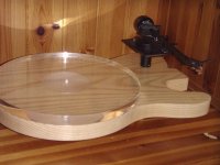
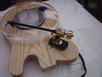
i now have some recordings MP3 of the floppy drive motor on a turntable so you can check the sound out
i dont think i can upload to DIY forum so....just email me if you want to hear it
also i have done a before and after recording of what differance an arm rewire makes if any1 wants to hear just email me
i have made some various pully sizes from plastic if any 1 needs some
best wishes
j7
audioorigami@gmail.com

hi
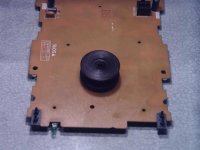
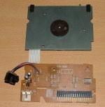
you have what i call the inverted type floppy ...with just the spindal sticking out ...this will make a fine motor for turntable
u need to use this end to mount a pully on ...u will need flaten the surface or pull of the existing pully ...to help mount your new 33/45rpm pully

you have what i call the inverted type floppy ...with just the spindal sticking out ...this will make a fine motor for turntable
u need to use this end to mount a pully on ...u will need flaten the surface or pull of the existing pully ...to help mount your new 33/45rpm pully
the long awaited part 3 is now ready
http://www.audioorigami.co.uk/FloppyProject/FloppyDIYMotor3.htm
thanks for your suport
best wishes j7
http://www.audioorigami.co.uk/FloppyProject/FloppyDIYMotor3.htm
thanks for your suport
best wishes j7
Attachments
that would be part 2.
http://www.audioorigami.co.uk/FloppyProject/FloppyDIYMotor2.htm
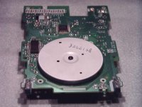
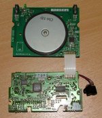
I found this 800ohm resistor inline to the motor controller…
(by jumpering each resistor with a 1000ohm resistor to see if any speed change was possible)
Each floppy will be different…so if you want to try varying the speed you will need spend a few minutes checking
")
http://www.audioorigami.co.uk/FloppyProject/FloppyDIYMotor2.htm
I found this 800ohm resistor inline to the motor controller…
(by jumpering each resistor with a 1000ohm resistor to see if any speed change was possible)
Each floppy will be different…so if you want to try varying the speed you will need spend a few minutes checking
i wet my finger and put over the resistors to find out what resistor changes the speed fast
Clever.
- Status
- This old topic is closed. If you want to reopen this topic, contact a moderator using the "Report Post" button.
- Home
- Source & Line
- Analogue Source
- New EASY DIY brushless motor