I just ordered a couple of filament supplies from Rod. My understanding is that the supply is comprised of a gyrator followed by a CCS, and that the filament is hooked between the gyrator and the CCS, as follows:
a)
filtered DC positive --> gyrator --> tube filament --> CCS --> filtered DC negative
My question is, why is the tube filament not connected after the CCS, where the line rejection is much higher; like this:
b)
filtered DC positive --> gyrator --> CCS --> tube filament --> filtered DC negative
I have measured an implementation of a simple gyrator/ccs supply hooked up as version a) above and the ripple on the tube filament is much higher than if hooked as in b). We're talking 20mV p-p for a) and below 30uV p-p for b).
So then, why is a) used by everybody?
Measuring ripple to ground rather than across the filament itself might possibly give a misleading result. Since the filament current flows in a closed loop the order should not make a difference from the standpoint of ripple, Rod's implementation does have a significant benefit in terms of the audio current which is common mode however - it keeps it out of the filament raw supply and isolates potential sources of line born EMI..
I'm using a pair of Rod's CCS in my new amps to power the GM70 output tube filaments.. (3A/20V)
Hi Relu,
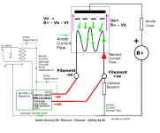
I'm probably wearing out my old diagram, but I've attached it again to show the noise paths that the regulator is trying to deal with.
Noise appearing on either side of the raw filament supply (+ or -) can creep into the circuit. Having a CCS on one side, and a gyrator on the other forms a noise-blocker for both paths. This might be mains noise, or rectifier recovery pulses.
With high frequency mains noise, it usually arrives as common-mode. BUT, if the + and - wiring follows different paths, it may not remain in common mode.
With fixed bias, one end of the filament is grounded, but the gyrator is still working hard to avoid circulating noise currents, and to block noise from getting into the CCS section, allowing the CCS to do a better job.
However, if you would like to try the regulator connected in the way you prefer, then it should still work. If you try it like this, please let us know how you like the sound in each connexion.
Probably best to test it in "normal" mode before trying that though.
Properly connected, with a decent transformer, and the raw dc prepared according to my Application Note, the Regulator should cut the noise across the filament all the way down to the microvolt level, even where you have ~200mV of incoming supply ripple.
I hope you enjoy the sound of the Regulators!
.
Attachments
Thanks guys (ZM, Kevin, and Rod).
Well, if only the differential voltage across the filament is what matters, then we'd be fine with AC heating, but we're not. Let's take Rod's diagram and a tube like type 26 as example, which assumes a cathode resistor for bias. All voltages wrt ground. The grid is at 0V DC, the positive side of the filament might be at 10V DC above ground while the negative side of the filament is at 8.6V DC. Type 26 tube needs about 1.4V DC at about 1.05A for the filament. All these are DC, but there is an AC component in the filament, which I measured to be around 7mV RMS. Yes, measured across the filament, the AC component is probably in the uV level. However, any difference in voltage potential between grid and cathode (filament) translates directly into current flow between plate and cathode. That's the reason why AC heating is a problem, no? Perhaps the low level of the AC component is what makes it un-noticeable.
As for the noise coming up ground... well, if the ground has low frequency components which the CCS can actually block, then that ground is really bad. High frequency noise coming up the ground connection will pass through the CCS without a problem, but can be addressed by other means.
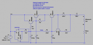
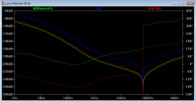
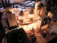
They way I see it, it should be better to connect the filament after the CCS. I'll test with my prototype supply if I get the time in the next few days, since Rod's supplies haven't arrived yet. For the curious, attached is my filament supply, in which I preferred to use a capacitor multiplier rather than a gyrator. It's very vanilla but it's very stable and filters really well, which the simulation attached gives an indication of.
Well, if only the differential voltage across the filament is what matters, then we'd be fine with AC heating, but we're not. Let's take Rod's diagram and a tube like type 26 as example, which assumes a cathode resistor for bias. All voltages wrt ground. The grid is at 0V DC, the positive side of the filament might be at 10V DC above ground while the negative side of the filament is at 8.6V DC. Type 26 tube needs about 1.4V DC at about 1.05A for the filament. All these are DC, but there is an AC component in the filament, which I measured to be around 7mV RMS. Yes, measured across the filament, the AC component is probably in the uV level. However, any difference in voltage potential between grid and cathode (filament) translates directly into current flow between plate and cathode. That's the reason why AC heating is a problem, no? Perhaps the low level of the AC component is what makes it un-noticeable.
As for the noise coming up ground... well, if the ground has low frequency components which the CCS can actually block, then that ground is really bad. High frequency noise coming up the ground connection will pass through the CCS without a problem, but can be addressed by other means.
They way I see it, it should be better to connect the filament after the CCS. I'll test with my prototype supply if I get the time in the next few days, since Rod's supplies haven't arrived yet. For the curious, attached is my filament supply, in which I preferred to use a capacitor multiplier rather than a gyrator. It's very vanilla but it's very stable and filters really well, which the simulation attached gives an indication of.
Attachments
The 4 big problems with ac:
1. The large voltage swing across the filament causes corresponding changes in the grid-cathode voltage, as you noted. The (constantly varying) filament voltage also changes the effective localised anode-to-cathode voltage, both effects producing hum and "second-harmonic of hum" cross-products in your music signal. The size of the problem is directly related to the ac voltage. The problem is quite noticeable when the ac voltage is 5V, quite miniscule in the uV to mV level.
2. With ac, the only noise-blocking method you can adopt is chokes - which have only a minor and band-passed effect. Mains noise, including coupled noise from B+ rectifier pulses, mostly marches right in.
3. The filament voltage gradient (constantly varying if ac-heated) produces a music-signal voltage across the filament. If ac-heated, this voltage drives a music-signal current through the transformer's secondary, where it sees the parasitic inductance of the winding, and the stray-capacitance to ground. An unwanted EQ-network, in other words, or perhaps a tuned-RF sniffer coil, according to its properties!
4. The cathode current (ie music signal) is flowing in the same internal wiring (of the DHT) and through the same pins as the filament current. Therefore, if the filament supply carries current noise (as opposed to voltage noise), this will be DIRECTLY mixed with your music signal. If your 1A supply has 0.1% current noise, that's 1mA. But think about what 1mA of noise does to a 60mA 300B cathode current, or 1mA in the 6mA cathode current in a 26 DHT...
My Regulator kits are designed to tackle all of those four problems. The design has a special focus on blocking HF noise. Judging from what folks around the world are saying about the sound, it seems to work.
My choice
Hello folks.
After several experiments I have concluded to use a rather simplistic approach. The disadvantage is that you have to be a coil winder, as there is no chance for the average DIYer to make things this way.
I am using tube rectification for the filaments (up to 3.3A) but the same could be done with solid state rectification. After the rectifier tubes or diodes and the filtering cap I am using a CCS and right before the filament I am using a common mode choke. Filament noise is common mode so a common mode choke blocks this kind of noise and CCS does the great part of AC filtration.
This method sonically outperforms every other method with electronics as the choke blocks practically filament noise and it is a passive device with least sonic signature. On my 801A amp the power tube's choke is 22.5 Henries, very high value.
IMHO it is the best solution but winding 22.5H chokes carrying 1.25A of DC current, is not for the beginner or the average DIYer...
If you are able to wind your own coils/transformers, try it!
Hi,
Well done.
Crosstalk between filament and cathode is nothing new though often negected.
Ciao,
The 4 big problems with ac:
1. The large voltage swing across the filament causes corresponding changes in the grid-cathode voltage, as you noted. The (constantly varying) filament voltage also changes the effective localised anode-to-cathode voltage, both effects producing hum and "second-harmonic of hum" cross-products in your music signal. The size of the problem is directly related to the ac voltage. The problem is quite noticeable when the ac voltage is 5V, quite miniscule in the uV to mV level.
2. With ac, the only noise-blocking method you can adopt is chokes - which have only a minor and band-passed effect. Mains noise, including coupled noise from B+ rectifier pulses, mostly marches right in.
3. The filament voltage gradient (constantly varying if ac-heated) produces a music-signal voltage across the filament. If ac-heated, this voltage drives a music-signal current through the transformer's secondary, where it sees the parasitic inductance of the winding, and the stray-capacitance to ground. An unwanted EQ-network, in other words, or perhaps a tuned-RF sniffer coil, according to its properties!
4. The cathode current (ie music signal) is flowing in the same internal wiring (of the DHT) and through the same pins as the filament current. Therefore, if the filament supply carries current noise (as opposed to voltage noise), this will be DIRECTLY mixed with your music signal. If your 1A supply has 0.1% current noise, that's 1mA. But think about what 1mA of noise does to a 60mA 300B cathode current, or 1mA in the 6mA cathode current in a 26 DHT...
My Regulator kits are designed to tackle all of those four problems. The design has a special focus on blocking HF noise. Judging from what folks around the world are saying about the sound, it seems to work.
Well done.
Crosstalk between filament and cathode is nothing new though often negected.
Ciao,
That post is absolutely pointless without a picture of choke and/or complete filament supply!IMHO it is the best solution but winding 22.5H chokes carrying 1.25A of DC current, is not for the beginner or the average DIYer...
If you are able to wind your own coils/transformers, try it!
Thanks guys (ZM, Kevin, and Rod).
Well, if only the differential voltage across the filament is what matters, then we'd be fine with AC heating, but we're not. Let's take Rod's diagram and a tube like type 26 as example, which assumes a cathode resistor for bias. All voltages wrt ground. The grid is at 0V DC, the positive side of the filament might be at 10V DC above ground while the negative side of the filament is at 8.6V DC. Type 26 tube needs about 1.4V DC at about 1.05A for the filament. All these are DC, but there is an AC component in the filament, which I measured to be around 7mV RMS. Yes, measured across the filament, the AC component is probably in the uV level. However, any difference in voltage potential between grid and cathode (filament) translates directly into current flow between plate and cathode. That's the reason why AC heating is a problem, no? Perhaps the low level of the AC component is what makes it un-noticeable.
As for the noise coming up ground... well, if the ground has low frequency components which the CCS can actually block, then that ground is really bad. High frequency noise coming up the ground connection will pass through the CCS without a problem, but can be addressed by other means.
They way I see it, it should be better to connect the filament after the CCS. I'll test with my prototype supply if I get the time in the next few days, since Rod's supplies haven't arrived yet. For the curious, attached is my filament supply, in which I preferred to use a capacitor multiplier rather than a gyrator. It's very vanilla but it's very stable and filters really well, which the simulation attached gives an indication of.
Ikoflexer:
Interesting design! Simple and with very good performance.
I am curious at your listening impressions.
Two extra listening tests I would advise you is to disconnect C3 to make Q4, Q1 a real Darlington. Measured/simulated performance will be less, but I expect it to sound better. Also you can omit R7 to raise Hfe of the darlington, ofcourse when everything remains stable. This could also enhance sonic performance.
Peter
That post is absolutely pointless without a picture of choke and/or complete filament supply!
It is rather simple:
Rectifier tubes - 1st filter cap - differential choke - 2nd filter cap - CCS - common mode choke - tube
With rectifying diodes:
Diodes - filter cap - CCS - common mode choke - tube
I will try to upload some pictures later.
I know. I was just joking around a little. But a picture would be great.It is rather simple:
Because I suppose it must be enormous.I know. I was just joking around a little. But a picture would be great.
Yes,
it is enormous indeed!
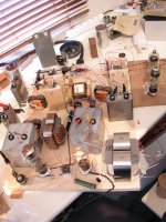
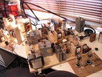
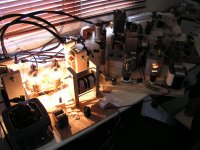
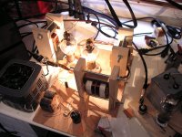
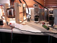
Below you will find some attached pics.
This is the 801A amp I'm building for a friend. Power tube 801A is driven in A2 by Emission Labs 30A tube. Tubes rectification throughout. This is quite possibly one of the very few power amps around where both High Voltage and filaments (of both tubes) are rectified with tubes! For the time being, 2 GE tubes ignite the output tube.
All iron pieces are manufactured to my standards and wound by myself. In the end each active stage will be supported by 9 (!) iron pieces, so the stereo set will have 36 transformers and chokes. The cost is enormous, considering the 6Watts of output power.
I have listened to almost anything on filaments supply. The - hands down - best solution is to use the following sequence:
Rectifying tubes->1st filter cap->differential choke->2nd filter cap->very big common mode choke->filament.
Differential choke is a must in order to avoid startup stress on rectifying tubes. 1st filter cap is only 1000uF but up to 3300uF is allowed. I have some other rectifying tubes with mercury, where the 1st filter cap must be limited to 1000uF.
Unfortunately the filament voltage must be stabilized so a CCS is unavoidable, otherwise filament voltage fluctuates besides allowed limits. This deteriorates the sound a little bit but there is no way to escape from it.
This is the most crazy solution to filaments heating. Unfortunately, it is by a ***huuuge*** margin the best performing sonically. Nothing can come close to its performance. Why on earth the most crazy solution tends to sound the best?
Has anybody tried anything similar?
Attachments
Unfortunately the filament voltage must be stabilized so a CCS is unavoidable, otherwise filament voltage fluctuates besides allowed limits.
cool project
Use a DC servo around your CCS loop and it will stabilize the whole
good luck


Yes,
it is enormous indeed!
Below you will find some attached pics.
This is the 801A amp I'm building for a friend. Power tube 801A is driven in A2 by Emission Labs 30A tube. Tubes rectification throughout. This is quite possibly one of the very few power amps around where both High Voltage and filaments (of both tubes) are rectified with tubes! For the time being, 2 GE tubes ignite the output tube.
All iron pieces are manufactured to my standards and wound by myself. In the end each active stage will be supported by 9 (!) iron pieces, so the stereo set will have 36 transformers and chokes. The cost is enormous, considering the 6Watts of output power.
I have listened to almost anything on filaments supply. The - hands down - best solution is to use the following sequence:
Rectifying tubes->1st filter cap->differential choke->2nd filter cap->very big common mode choke->filament.
Differential choke is a must in order to avoid startup stress on rectifying tubes. 1st filter cap is only 1000uF but up to 3300uF is allowed. I have some other rectifying tubes with mercury, where the 1st filter cap must be limited to 1000uF.
Unfortunately the filament voltage must be stabilized so a CCS is unavoidable, otherwise filament voltage fluctuates besides allowed limits. This deteriorates the sound a little bit but there is no way to escape from it.
This is the most crazy solution to filaments heating. Unfortunately, it is by a ***huuuge*** margin the best performing sonically. Nothing can come close to its performance. Why on earth the most crazy solution tends to sound the best?
Has anybody tried anything similar?
That is so completely over the top that I must applaud you.
That is so completely over the top that I must applaud you.
Thank you very much for your comments.
Peter.
Very impressive indeed!
I'd wind my own chokes, but can't find cores. Where do you get your cores from?
This is a bit off topic, but do you wind your own output transformers as well?
Hello from Athens, Greece.
You can buy very good quality cores from Alphacore USA.
Link is C-cores Stock
All signal transformers' iron cores seen here are ordered to a factory in Hong Kong, they produce the magnetic material I want and these are custom order. It is not possible to acquire those cores as the material is proprietary. It is not CRGO, not Permalloy, not Supermalloy, not Nanocrystalline etc.
I wind all kinds of chokes and transformers by myself. Each stage of this amp is equipped with
- 1x filament rectifying tube filament transformer (2.25VAC)
- 1x filament rectifying tube high voltage transformer (~35VAC)
- 1x differential choke for filament ignition
- 1x common mode choke for filament ignition
- 1x HV rectifying tube filament transformer (2.5, 4 or 5V)
- 1x HV rectifying tube transformer (~2x700 VAC)
- 2x differential chokes for HV filtration
- 1x signal transformer (interstage or output)
Both interstage and output transformers have ultra wide bandwidth. I ended up winding whatever I want because there exists no OPT or IST that could come close to my standards both to measurements and sonic performance.
I hope all the above help a little bit.
Have a nice day!
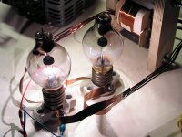
Wow, very very cool.. I think you are the first person I have seen in modern history to use tungar bulb rectifiers.. Certainly unique, can you share some schematics with us? I have no gut sense of how to implement rectification with tungar bulbs - can they handle significant capacitance (presumably they can since they were commonly used in antique battery chargers) and I assume you have lots of low dcr choke action going on.. Very lossy voltage wise or not?
- Home
- Amplifiers
- Tubes / Valves
- New DHT heater