Hi Rod
Are there options that could be used with DHTs of
7.5 V, 1.25 A and
4.0 V, 0.6 A
Cheers
Hi Otto - There is certainly a Standard Build 7.5V/1.25A for 10Y and 801A etc. Don't recall a 4V 600mA though, what do you have there?
All will be ready once I'm finished polishing...
Very basic question about voltage vs current.
I guess this might has been brought up before, but I just can not find it effectly, sorry. (The key words "volgate" & "current" are two words lead to almost everything... )
When filament is supplied by a current source, which is more important: [current flow] or [voltage across filament] ?
I experimentally tried a simple CCS (Vreg: LD1085) on the filament supply on my 2A3. I use a 1 Ohm (1%) resistor for initial trial and get a 'perfect' 2.5V/2.5A after a short while of warm-up (the voltage is slightly higher at the first one or two minutes). Then I plug in the tube, and get a slightly higher voltage, 2.6V across the filament.
The reference voltage (between pin adj and out) is well maintained at 1.247 V (rated 1.25), and they are connected by a fixed 0.5 Ohm resistor. This resistor is in series with the whole circuit, so it should see all of the current flow, except the tiny setting current on pin-Adj which can be ignored.
The resistor is measured and it's precise 0.5 Ohm, so the current flow should be 2.494 A. Now I got 2.6V on the filamnent, this should mean the resistance is 1.04 Ohm, right?
So, now what? Should I turn down the current to 2.4A to get 2.5V across, or just let it flow 2.5A no matter what?
With the tube at normal idle conditions (plate voltage applied, design current flowing) I would set the current such that you get 2.5V across the filament. The manufacturer originally designed the filament to operate with a voltage source, so application of rated voltage would be good.
Of course, you can experiment with starved filament operation, but fundamentally you pursue a target voltage and let the current fall where it will.
The design goal behind using a CCS to drive the filament is not to get the "correct" current to flow, but to have a high source impedance that the filament sees.
...
The manufacturer originally designed the filament to operate with a voltage source, so application of rated voltage would be good.
....
Indeed. Good point. Will do.
")
As to starving, I incidentally experienced that with bad results on my 2A3 amp. That tiny power amp seems hungry for every bit of emission it can have.
Posted very long ago
Sorry for digging this out after such a long time.
I've subscribed this thread and read through / searched several times, but I haven't found the reason for this:
So, Rod,
What is the reason for gyrator on + / CCS on - ? Does it matter if the sequence is the opposite? (ccs on + / choke on - )
Thanks,
CLS
Sorry for digging this out after such a long time.
I've subscribed this thread and read through / searched several times, but I haven't found the reason for this:
(this is #35 post, July 2004) http://www.diyaudio.com/forums/tubes-valves/38248-new-dht-heater-4.html#post446973...
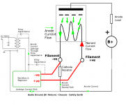
I briefly considered a complementary current source to isolate both filament terminals, but soon realised a much better circuit with current sinking on the negative, and a gyrator (aka electronic choke) to reject ripple on the positive supply.
...
So, Rod,
What is the reason for gyrator on + / CCS on - ? Does it matter if the sequence is the opposite? (ccs on + / choke on - )
Thanks,
CLS
There is one consideration - which filament terminal [+ or -] shall we connect to the b+ circuit [ie GND]?
Need some background first though - [skip the paragraphs between the stars if you want to go straight to the answer!]
****************************
There's [at least] 4 reasons to use athe CCS/gyrator architecture:
1. Establish a high dynamic impedance between the Filament terminals. I don't know if there's some kind of micro-phasing effect, or something else, but it is certainly important. If you connect this circuit to a DHT and enjoy the wonderful sound for a while, then try putting a 1uF across the filament - the sound is degraded below AC standard.
2. Minimise hum without interfering with the anode current. The gyrator is an open-loop regulator, while the CCS has feedback network which is not in contact with the filament. There's a big difference. I tried circuits with opamps and other feedback methods, even rolled off as a 2Hz servo, but if the feedback network is in contact with the filament, you lose out on the sound. One can only assume that the anode current is being sensed by the feedback, partly, and causing interaction with the CCS pass transistor.
3. Because the filament is the cathode, and the cathode is part of the DHT's input [the grid-cathode voltage drives the DHT], imagine having the input circuit snaking around on long wires, picking up fields, and capacitively-coupling the input circuit to ground through horrible dielectrics (like PVC wiring). But that's just what happens with AC-heat, and dc-rectified heating. That is why ac-heat sounds different with different transformers - although it always sounds bad compared to CCS heat.
THe CCS/Gyrator transistors buffer the filament from the filament trafo & rectifiers, and gives more consistent, and hugely better sound.
4. Current limited control prevents big turn-ON current. My 300Bs measure 0.7-ohm cold, so they would see ~8-Ampere peaks at startup. That maybe why mine have already lasted nearly 12 years constant use, whereas filament breakage seems to be the biggest failure mode for 300Bs.
****************************
So to answer your question, the CCS/gyrator addresses the points 1 to 4, so you build one. To get good performance, the transistors must work at very low voltage, with lowest base current. That always favours NPN [or n-channel FET] above PNP or P-channel. connect it to your circuit. So the Gyrator must be on the positive, and the CCs must be on the negative.
you could build the circuit with PNPs, and reverse the polarity, but the parts cost much more, and the performance is weaker.
Next you have to decide to connect the +ve terminal to ground [or cathode resistor] or -ve. Because of point 3 [leakage of anode current] you would Ground the side that is not so well buffered (CCS or Gyrator). This is really a matter to experiment with, and depends a lot on the wiring and layout of your amplifier - it works both ways, but sounds better only one way, usually. When you try this, be sure Left and Right channels are wired the same, or the sound becomes very strange, like out-of-phase.
Hi Rod,
Thanks a lot for your thorough explanation TBH, in my current project amp, I don't have enough voltage for your discrete circuit I have less than 2V to spare. So I use a low drop out Vreg-base CCS (LD1085) and a choke (only 2.4mH) on both ends of the 2A3's filament.
So, for now, I'm not in the trouble of choosing between PNP and NPN. Major issue would be the anode current leakage. (or the not enought impedace of that little choke...)
Your drawing is excellent and those arrows in the tubes are just the same as the picture in my mind! I'll think more about the leakage path and do some experiments. Thanks again
One more question: turn-on current control is surely a good thing, but how long does it take to rise to full voltage in your circuit?
In my current setting (ccs by Vreg), the voltage rising seems too slow (I think). It takes about 30 sec. to rise to 2.3~2.4V, and then, equal or slightly more time for reaching the 2.5V final goal. It should be OK to have 2.3V in the first 30 sec. when the B+ is now full on. I can't help thinking it must be better to have the filament fully ready slightly ahead of the B+, instead of the opposite.
Thanks a lot for your thorough explanation
TBH, in my current project amp, I don't have enough voltage for your discrete circuit I have less than 2V to spare. So I use a low drop out Vreg-base CCS (LD1085) and a choke (only 2.4mH) on both ends of the 2A3's filament. So, for now, I'm not in the trouble of choosing between PNP and NPN. Major issue would be the anode current leakage. (or the not enought impedace of that little choke...)
Your drawing is excellent and those arrows in the tubes are just the same as the picture in my mind!
I'll think more about the leakage path and do some experiments. Thanks again One more question: turn-on current control is surely a good thing, but how long does it take to rise to full voltage in your circuit?
In my current setting (ccs by Vreg), the voltage rising seems too slow (I think). It takes about 30 sec. to rise to 2.3~2.4V, and then, equal or slightly more time for reaching the 2.5V final goal. It should be OK to have 2.3V in the first 30 sec. when the B+ is now full on. I can't help thinking it must be better to have the filament fully ready slightly ahead of the B+, instead of the opposite.
Ah, yes, I already had damper diode. I use 6AU4GTA in this amp. It takes about 30 sec. to reach the B+ voltage. However its start up behavior is not 'linear'. In my amp, there's nothing in the first 20 sec. or so, then it starts to climb. In the next 10 sec. (or slightly more), it touches the goal.
On the other hand, the ccs filament supply (and filament) has a jump start (@ about 0.6~0.7V), then climbs linearly to about 90% target voltage (2.2~2.3V in mine). The final 10% takes pretty long to get to (about another 30 sec. or so).
Comparing the 2, there's a short period when the B+ reach 90% but the filament is only 60~70%. Only a couple of sec., though. Meantime, the anode current is low, too. I think it's caused by the not enough emission. And it's obvious the anode current keeps tracing the filament voltage in the final warm-up stage. Overall, it takes about 1~1.5 min. in my amp to reach stable operation.
I guess it's no big deal, as everything is changing in relatively slow pace. Though I'm still planning to add a separate filament transformer and delay B+ further with timer. Complexity and cramped chassis are holding me back, considering, considering....
I guess it's no big deal, as everything is changing in relatively slow pace. Though I'm still planning to add a separate filament transformer and delay B+ further with timer. Complexity and cramped chassis are holding me back, considering, considering....
We know
Rod let me know when ready, I have ask a lot time ago....
We know
Rod let me know when ready, I have ask a lot time ago....
Hi! nicoch46!
Please Wait him! He is preparing you theories and facts about DHT filamnet! I think so, too is a busy job!
Listen
Read phonetically
Hi Rod
I've not posted here before, but will certainly be ordering two 300B kits when you're ready.
Until recently I was using just unregulated dc heating- though with centre tapped transformer windings, a BYV32E rectifier, each half bipassed with 1n2 silver mica caps, 10000u Panasonic FC, and 2 x 4700u Black Gate NX caps directly across the filament. For such an arrangement, the careful component selection gave good performance. I then installed a 6A rated, 1,4mH common mode choke to each filament supply, directly before the filament/BG cap. I was rewared with a considerable improvement in sound quality. A couple of months back I fitted some filament supplies from DiY Hifi Supply- 1085-based CCS’s but regulated to 5V out at dc. These were a definite step up in sound. But- and this is the reason I’m posting- after their installation I heard again “filament bong”- that ringing noise you sometimes get when suddenly switching the input signals off, most obvious over sensitive speakers. I used to get this, but realised that at some stage it had disappeared! I’d guess this was after the common mode filters were installed. Is this possible, and does it have any implications for your design? I subsequently re-installed the common mode filters, but before the regulators, and noticed no obvious effects at all
Sorry if this is a bit left field
Thanks
Paul
Hi Rod
A couple of months back I fitted some filament supplies from DiY Hifi Supply- 1085-based CCS’s but regulated to 5V out at dc. These were a definite step up in sound. But- and this is the reason I’m posting- after their installation I heard again “filament bong”- that ringing noise you sometimes get when suddenly switching the input signals off, most obvious over sensitive speakers. I used to get this, but realised that at some stage it had disappeared! I’d guess this was after the common mode filters were installed. Is this possible, and does it have any implications for your design? I subsequently re-installed the common mode filters, but before the regulators, and noticed no obvious effects at all
Thanks
Paul
That's an interesting observation. I believe the 'bong' is just mechanical oscillation of the filament caused by sharp changes in anode-current [a turn-OFF click]. Like tapping a resonant structure. With voltage-regulated dc, the capacitor connected across the filament terminals will absorb the component of the pulse that differs between the 2 ends of the filament - and most probably moves the oscillation frequency to a new higher one, determined by the capacitor resonances (mechanical and electrical) or the regulator transient response (which is usually unpleasant to audio signals).
I would associate the suppression of the 'bong' with bad sound, since the mechanical resonance is likely to be more natural than cap/regulator responses.
I did try an interesting test a few years ago on a LP2 DHT driver: connect a damping resistor across the filament, and see whether there is some value of R that damps the resonances without them reappearing somewhere else. The LP2 (CV1166 Tungsram UK version) is a very microphonic DHT, and my notes suggest it preferred a few hundred ohms across it, with the sound degrading for higher and lower values.
If you have time, try that, with 50, 100, 200, 500, 1K [carbon composition for minimal spurious inductance] and let us know!
Ah, yes, I already had damper diode. I use 6AU4GTA in this amp. It takes about 30 sec. to reach the B+ voltage. However its start up behavior is not 'linear'. In my amp, there's nothing in the first 20 sec. or so, then it starts to climb. In the next 10 sec. (or slightly more), it touches the goal.
On the other hand, the ccs filament supply (and filament) has a jump start (@ about 0.6~0.7V), then climbs linearly to about 90% target voltage (2.2~2.3V in mine). The final 10% takes pretty long to get to (about another 30 sec. or so).
Comparing the 2, there's a short period when the B+ reach 90% but the filament is only 60~70%. Only a couple of sec., though. Meantime, the anode current is low, too. I think it's caused by the not enough emission. And it's obvious the anode current keeps tracing the filament voltage in the final warm-up stage. Overall, it takes about 1~1.5 min. in my amp to reach stable operation.
I guess it's no big deal, as everything is changing in relatively slow pace. Though I'm still planning to add a separate filament transformer and delay B+ further with timer. Complexity and cramped chassis are holding me back, considering, considering....
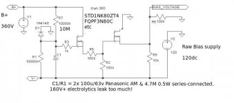
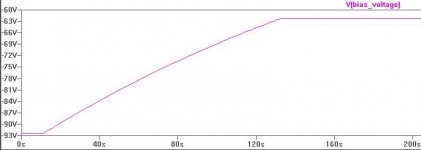
CLS, timer for B+ may take up a lot of space, so how about a slow Bias voltage? Biasing the DHT to cutoff will protect the cathode while it warms up.
This circuit is dimensioned for 300B, but could be adapted for any DHT. With no B+, it starts with about -95V, which is almost cutoff for 360V 300B. The bias takes 2 min to get to the -63v.
Attachments
- Home
- Amplifiers
- Tubes / Valves
- New DHT heater