Stefano,
What is the diameter of the flywheel in your sketch?
looks like 180 then 140 or 110?
I would like to make a brief comment on the motor, we will be using this motor at roughly 20% of the rated speed, it will not operate at the same efficiency at this speed. Motors with more pole pairs are designed to run at slower speeds.
We should ask the manufacturer of the motor about excessive heat being generated at this speed with this load applied.
I will try to supply a sketch of my idea to support the weight of this flywheel without a flange bushing or a thrust bearing tomorrow.
Thanks,
Ted
Stefano,
What is the diameter of the flywheel in your sketch?
looks like 180 then 140 or 110?
I would like to make a brief comment on the motor, we will be using this motor at roughly 20% of the rated speed, it will not operate at the same efficiency at this speed. Motors with more pole pairs are designed to run at slower speeds.
We should ask the manufacturer of the motor about excessive heat being generated at this speed with this load applied.
I will try to supply a sketch of my idea to support the weight of this flywheel without a flange bushing or a thrust bearing tomorrow.
Thanks,
Ted
Hi Ted thank you very much for your comment.
On my sketch, the flywheel has a diameter of 140mm, while pulley 14mm.
You bring up a very good point about low speed and heat. I have talked to the manufacturer about that and they said that the precious metal version can run at any low speed without any problem with heat, while the graphite version will have to run at higher speed. The manufacturer also specified that these types of motors are already used by other manufacturer at low speed some even lower with great success, just thought of mentioning this.
I will be looking forward to seeing your sketch. Thanks for your interest and support on this.

From another thread and in this series of pictures from this year's Fickelfest 2014, I saw this motor island by Frank Schroeder. Very interesting. It's belt driving a wheel direct coupled to the platter, which reminds me of the VPI and Teres Verus systems. Some pictures are not directly aimed at the motor but you can still see a glimpse of the parts.

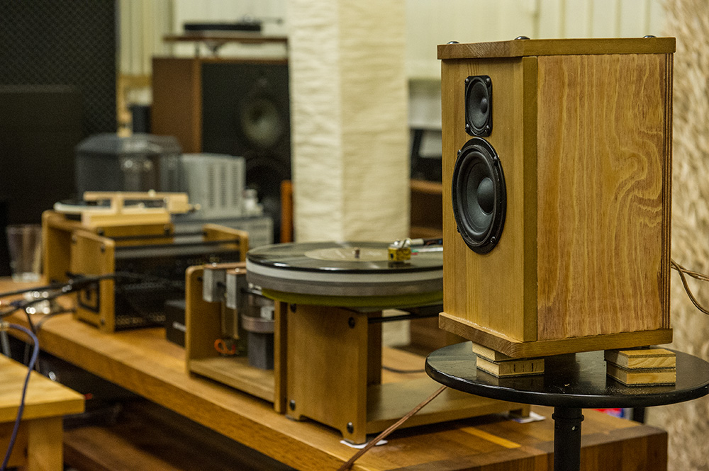
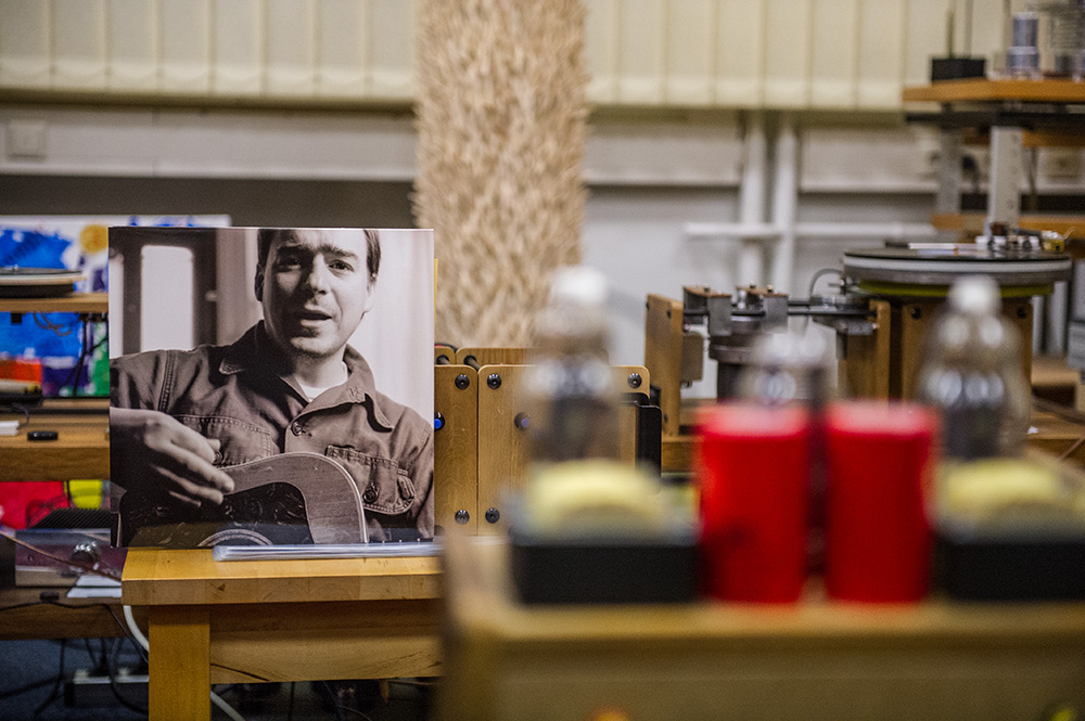


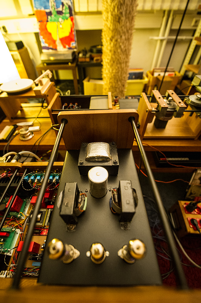

I hope the above are not off topic.
.
I hope the above are not off topic.
.
no, no absolutely not off topic. I personally always enjoy the pictures you find of other TT systems, please continue posting.
Basically this is similar to the VPI RIM drive. though, isn't Teres Verus just a pulley directly driven by the AC motor in contact with platter with no belt?
Basically this is similar to the VPI RIM drive. though, isn't Teres Verus just a pulley directly driven by the AC motor in contact with platter with no belt?
for your idler you might want to consider torque activated drive. basically this means that when the motor is at rest the idler is off the platter rim but when you engage the motor the idler is swung into action and pushed against the platter rim by the torque/rotation of the motor.
for your idler you might want to consider torque activated drive. basically this means that when the motor is at rest the idler is off the platter rim but when you engage the motor the idler is swung into action and pushed against the platter rim by the torque/rotation of the motor.
Like a spring mechanism like a garrad? To prevent that the o-ring becomes flat? This is on a separate pad, I am not sure what you meant. Do you mind explain further?
the idler sits at the arc or the motor spindle on sliding plate (you can use a spring to engage back pressure for off state). when the motor in engaged the idler is forced into action by the spinning of the motor and then slides round till it comes in contact with the rim of the platter, we are only talking 1-2mm of clearance that is needed when in rest state. if you take a motor shaft and try to turn a disc without the disc being held in the centre the disc will want to rotate round the motor shaft. you use this force in your favour.
Would you use this mechanism to engage the and disengage the system without having to move the pad or did you imply it to have another functionality?
Sorry if it is a dumb question
My idea, and tell me if I am wrong, would be to have it as simple as possible to make it and without any moving parts such as springs as I think they affect the sound. Do you think I am wrong on this?
Sorry if it is a dumb question
My idea, and tell me if I am wrong, would be to have it as simple as possible to make it and without any moving parts such as springs as I think they affect the sound. Do you think I am wrong on this?
yes to stop the idler surface being distorted when at rest.
gotcha!
Let me know if this makes sense to you or not, would it be easier to move the pad once done listening off from the platter? Something we need to still define though. and here is where your mechanism could come into play, is something to disengage the motor pulley from the idler wheel.
Do you think we can maybe sacrifice a little bit of the ease of use and have a set of screws on the flange that disengages the motor from the pad so that it can slide 3-4 mm to the left or right to adjust proper tension and also remove the motor in contact from the wheel when platter is not used?
I think this is a little more elaborated to use, but wouldn’t it be easier to make and probably having less moving part on the mechanism? Let me know if this makes sense or not.
yes its to engage and disengage the idler.
your sort of correct but you will have to use some sort of mechanism to disengage the idler be it lever or whatever. levers ring/vibrate (unless made of wood) just like springs and no matter what system you use its going to have to be a pivot/sliding rail of some kind so you will have moving parts unless you leave the idler in contact at all times.
the simpler the better in my book and this is why i mentioned using spinning action of the motor. but i could be wrong.
It might be wise to use very short and stiff O ring belt connection at the motor only.
The Achilles heel of this design is the higher speed motor and a way to eliminate its vibration
This would cure the touching problem and if the belt is stiff enough and short in length, it shouldn't flex to much to defeat the design idea of a tight coupling. Vibration should be reduced also
This way you kill 2 birds with one stone.
The main idler and support structure would just be pulled away or screwed in and out when not in use.
Are you stuck on the way VPI does this or have you looked at Lenco's and Thoren's way of rotating a platter?
Consider also the Dia. of different platters and enough speed range to compensate
My SOTA vacuum,s are 12",but an Ariston rework I have is 11.750" Dia.
Regards
David
Sorry Arch-don't understand your comment. The idea is that the motor is in a 'heavy' housing and the pulley presses against the platter rim when in use. The lever then just tilts it away when not in use-this avoids 'flats' on the pulley wheel.
I agree with that.
But suppose you put only two feet under the housing, then the third point of equilibrium is the idler wheel against the rim when running. So the pressure of the O-ring is only made by the weight of the entire housing.
When not in use you disengage the pulley by the mean you want, balancing the housing the other side.
For some reason I don't see this very practical, but I might be wrong. I think if the motor pad is sufficiently heavy, once it set against the platter it won’t move anywhere.
One thing overlooked so far is the importance for leveling everything as much as possible, whether it sits in equilibrium or sits statically against the platter. In fact, if the RIM for instance is out of level, it will wobble against the platter causing unwanted noise.
Am I wrong?
The base of the pod will/should have feet for proper, easy and solid adjustments.

- Status
- This old topic is closed. If you want to reopen this topic, contact a moderator using the "Report Post" button.
- Home
- Source & Line
- Analogue Source
- New DC drive system for TT -RIM drive- starts here!!!