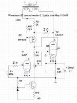
Almost. (talking scaled g2/g1 drive) The output tube g2 would need a Mosfet follower to shield the original P-Mosfet driver from the g2 current. (driver then still running at constant current from the gyrator then).
OOPs, the two grids would be working at the same AC voltage that way. Some way needed to scale down the g1 drive. Maybe just a couple of high R's to make an attenuator down to the output cathode.
OOPs, the two grids would be working at the same AC voltage that way. Some way needed to scale down the g1 drive. Maybe just a couple of high R's to make an attenuator down to the output cathode.
Last edited:
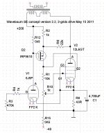
Here is a 2nd shot at the P-tube variant. V2 does the local feedback subtraction now (with an internal g2,g1 Mu factor), while P-channel M1 provides the loop gain as a cascode. One could say M1 is transparent now, since the same current comes out as what goes in. "Gyro" is the same gyrator setup as before to set the g1 bias for V3. Using a tube for V2 now removes the drive capacitance issue. The M1 cascode would likely have been used with the earlier setup anyway to deal with voltage drops. Since the V2/M1 stage is now non-inverting, the outer loop feedback had to go to the V1 cathode for correct phase. (I had mentioned a variant above with the outer loop fdbk going to the g2 of a pentode V1 earlier, when the P-channel stage was inverting.)
Attachments
Last edited:
- Status
- This old topic is closed. If you want to reopen this topic, contact a moderator using the "Report Post" button.
- Home
- Amplifiers
- Tubes / Valves
- New concept of a power amp