I always point UK people to this excellent independent supplier who stocks some of the Supertex chips at reasonable cost, and he matches for you as part of the deal;
http://www.ebay.ie/sch/big.daddy!/m...A5788&rt=nc&_trksid=p3911.c0.m14.l1513&_pgn=4
An occasional member here.
Edit: The forum seems to be mangling the URL, so you would have to do a search on seller big.daddy
Shoog
http://www.ebay.ie/sch/big.daddy!/m...A5788&rt=nc&_trksid=p3911.c0.m14.l1513&_pgn=4
An occasional member here.
Edit: The forum seems to be mangling the URL, so you would have to do a search on seller big.daddy
Shoog
Last edited:

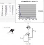
Something along these lines could work. I now place the gate stoppers inside the zener protection diodes, but the basic topology works quite well. You can run well over 100 mA total, as the DN2540 has a higher IDSS than the IXYS. Benefit to using the IXYS on top is two-fold: you allow greater Vds for the bottom device, and the capacitance of the IXYS is much smaller (Gary Pimm measured 2.25pF for the IXYS and 32pF for the DN2540).
Compare that capacitance to 167pF for the IXTP6N100D2, you could get away with a lot of paralleled IXYS and still have theoretically better performance. No doubt there is a law of diminishing returns, as well as cost.
The only trick is getting a bottom device suitable for currents greater than 150 mA. Possibly toss the IXTP6N100D2 in the bottom...
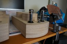
Attachments
If capacitance is a problem, what about other types of Ixys:
http://ixapps.ixys.com/DataSheet/DS100182A%28IXTY-TA-TP08N100D2%29.pdf
or
http://ixapps.ixys.com/DataSheet/DS100185B%28IXTY-TA-TP1R6N100D2%29.pdf
Maybe these are better suited for our project (yes, I will be building together with Paul Dune) as we "only" need 1000V and 200mA.
It will be insane to cook so much heat, but its a beautifull idea we have to try...
If i'm understanding it correctly, in a cascode setup, the capacitance of the upper (pass) device is no big problem. The lower device is in series with the upper, so the resulting capacitance of both is always lower than either.
The lower device can be less voltage, but since it is in series, not less current.
Correct?
Now all I have to do is find a working schedule and some calculations about the voltage the lower device has to process.
Paul
The lower device can be less voltage, but since it is in series, not less current.
Correct?
Now all I have to do is find a working schedule and some calculations about the voltage the lower device has to process.
Paul
If capacitance is a problem, what about other types of Ixys:
http://ixapps.ixys.com/DataSheet/DS100182A%28IXTY-TA-TP08N100D2%29.pdf
or
http://ixapps.ixys.com/DataSheet/DS100185B(IXTY-TA-TP1R6N100D2).pdf
Maybe these are better suited for our project (yes, I will be building together with Paul Dune) as we "only" need 1000V and 200mA.
It will be insane to cook so much heat, but its a beautifull idea we have to try...
Hey R.,
As I see both the datasheets, the parasitic capacitance is significantly less as with the OP device. But i'm not shure there is a problem in a cascode, providing the lower device has low capacitance.
Since we have them already, i'm going to try them anyway. Maybe starting at 100mA in combi with 10m45s, putting a 10 ohm resistor in series before the complete CCS, and measure carefully how much AC (signal) is visible there. Should be as little as possible, if the CCS is "ideal" there is only DC flowing thru this resistor.
Paul
Last edited:
Something along these lines could work. I now place the gate stoppers inside the zener protection diodes, but the basic topology works quite well. You can run well over 100 mA total, as the DN2540 has a higher IDSS than the IXYS. Benefit to using the IXYS on top is two-fold: you allow greater Vds for the bottom device, and the capacitance of the IXYS is much smaller (Gary Pimm measured 2.25pF for the IXYS and 32pF for the DN2540).
Compare that capacitance to 167pF for the IXTP6N100D2, you could get away with a lot of paralleled IXYS and still have theoretically better performance. No doubt there is a law of diminishing returns, as well as cost.
The only trick is getting a bottom device suitable for currents greater than 150 mA. Possibly toss the IXTP6N100D2 in the bottom...
Thanks for the schematic! Do you have calculations with it? (to get some approximate starting values for resistors)
Do I understand correctly that it doesnt mather wich of the two FETs has low Ciss? As they are in series?
Paul
Pauldune, I believe you are correct based on some fairly extensive experimentation. If the top fet has high Ciss it will pass AC, but if the lower device blocks it because it has low Ciss then all is good.
Also bear in mind Ciss decreases dramatically with a lot of devices as the voltage increases and the depletion zone gets wider.
Also bear in mind Ciss decreases dramatically with a lot of devices as the voltage increases and the depletion zone gets wider.
Seems to me is one would be pretty good as lower device:
IXTP02N50D
http://ixapps.ixys.com/DataSheet/98861.pdf
It has pretty low Ciss(120pF) , a fairly high cutoff Vgs (-5v) ,has 200mA Id minimal based on junction temp. If it is cool can handle op to 800mA; in the CSS it will be very cool with VDS of approx 5V/200mA. And it can handle some abuse because its a 500V device.
Am I right in my assumptions?
Paul
excess parasitic C is still a fundamental limitation even with cascode - the current to charge and discharge the parasitic C have to come out of your Id
only the current in the Cgs of the upper pass device can be substantially fulfilled by the local current loop if you use a floating Vbias returning the current to the control device source
do always use the lowest current rated/lowest parasitic C part that fits the job
only the current in the Cgs of the upper pass device can be substantially fulfilled by the local current loop if you use a floating Vbias returning the current to the control device source
do always use the lowest current rated/lowest parasitic C part that fits the job
Hi Paul,
Have you given that (IXTP02N50D) a try ??
King
No, not yet. Had to complete some other projects first...
@jcx Correct me if i'm wrong, but the two parasitic c's in a cascode are in series. If two capacitors are connected in series, the resulting C is always smaller than the smallest of the two. To me it looks like no problem, if one of the two c's is small.
Attachments
do always use the lowest current rated/lowest parasitic C part that fits the job
This is good advice. The lower the parasitic capacitance of the device, the better the high frequency impedance performance. What I've found with most of these depletion mode MOSFETs is they are best used between 5% and 30% of their rated Id. Outside of this the Rset resistor values become extreme on either end.
Attachments
Brilliant thread, lots of information I was looking after. Besides active plate loads, I'm currently trying to use a CCS to excite inductors (of the filter choke type) and the primary of SE OPT's with superimposed AC (C coupled) and DC (from CCS) for testing purposes. While Xpersephone2:
and Shoog:
addressed considerations upon device destruction, I'm still not sure if a simple free wheeling diode in parallel with the highly inductive DUT will provide enough protection against the catastrophic failure episodes I've been facing upon DC current suddenly cutting off. Do I need a special transient voltage surge suppressor, or a series zener/rectifier combination should suffice? Any advice will be welcome - thanks!
fbetti
"(Paralleling cascodes) will be expensive, and involve a bunch of dead MOSFETs in getting it right"
and Shoog:
"I've found that these devices need to be considered in light of turn on transients which can spike high and take them out of their SOP"
addressed considerations upon device destruction, I'm still not sure if a simple free wheeling diode in parallel with the highly inductive DUT will provide enough protection against the catastrophic failure episodes I've been facing upon DC current suddenly cutting off. Do I need a special transient voltage surge suppressor, or a series zener/rectifier combination should suffice? Any advice will be welcome - thanks!
fbetti
- Status
- This old topic is closed. If you want to reopen this topic, contact a moderator using the "Report Post" button.
- Home
- Amplifiers
- Tubes / Valves
- New CCS/ depletion mode MOSFETs available... experience anyone?